4OM-1322-006_w.pdf - 第104页
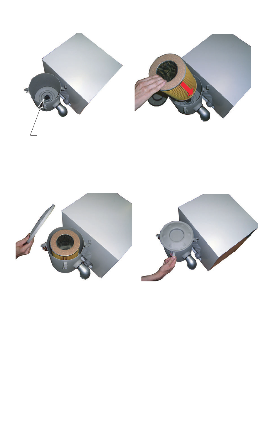
1-42 AKOEMT -ID (4) Set the filter such that the center hole of the filter can fit into the flange located at the rear side of the filter cover . Flange Section Fig. 4A59 (5) While holding the lid, engage the clip securely su…
1-41 AKOEMT-ID
4.1.3 Replacement Procedure of Blower Filter
Operation Procedure
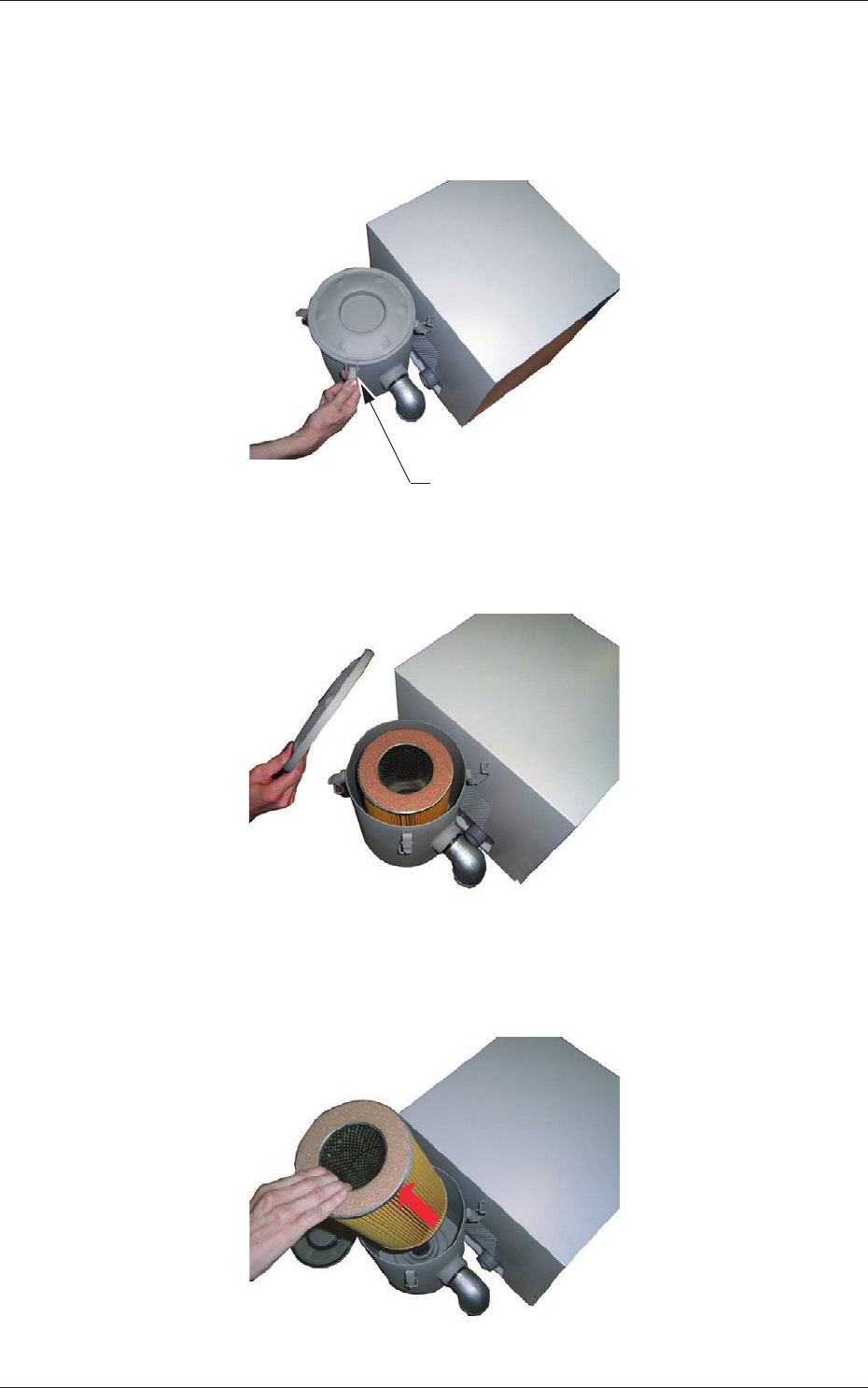
(1) Disengage the clips fastening the lid of the filter cover. (4 places)
Clip
Fig. 4A56
(2) Remove the lid.
Fig. 4A57
(3) Detach the filter and remove dust accumulated on the filter with an air
gun or a vacuum cleaner.
Fig. 4A58
0609-002
4.1 Replacement and Adjustment of Consumables
1-42 AKOEMT-ID
(4) Set the filter such that the center hole of the filter can fit into the flange
located at the rear side of the filter cover.
Flange Section
Fig. 4A59
(5) While holding the lid, engage the clip securely such that the flange
(located at the center of the lid) can fit into the center hole of the filter.
Fig. 4A60
0609-002
4.1 Replacement and Adjustment of Consumables
1-43 AKOEMT-ID
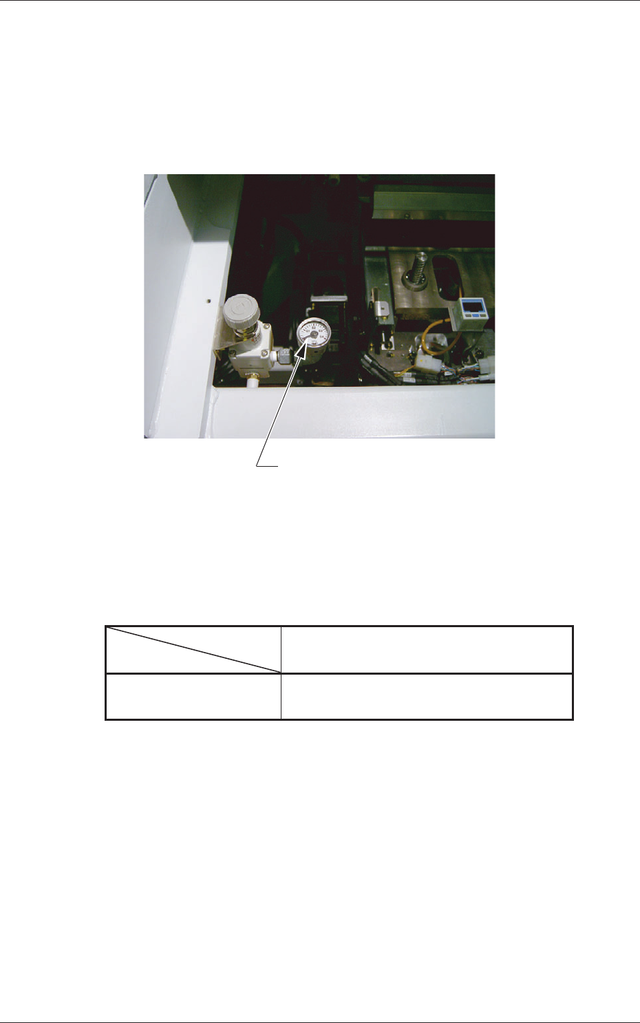
4.2 Adjustment of PCB Horizontal Clamping
When a thin PCB is used and the horizontal clamping force is strong, it may
be warped.
To avoid this, adjust the force with the pressure reducing valve which is
located at the front left (operator side) of the L Conveyor.
Pressure Reducing Valve
Fig. 4A61
Target Air Pressures Related to PCB Thickness
The values were obtained when the PCB size is "150 × 100", excluding a
PCB stopper.
Table 4A14
PCB Thickness
Air Pressure
0.5 1.0 1.5 2.0 (mm)
MPa 0.12 0.2 0.3 0.3
(kgf/cm
2
) (1.2) (2.0) (3.0) (3.0)
0609-002
4.2 Adjustment of PCB Horizontal Clamping