ASM-X-Spec-SX12V2-EN-DMS - 第27页
27 Smart Pin Support General Wide boards tend to deflect during placem ent such that, under certain circumstances, the compon ents can no lon- ger be pl aced with the desired accuracy . Highly curved PCBs also affect the…
26
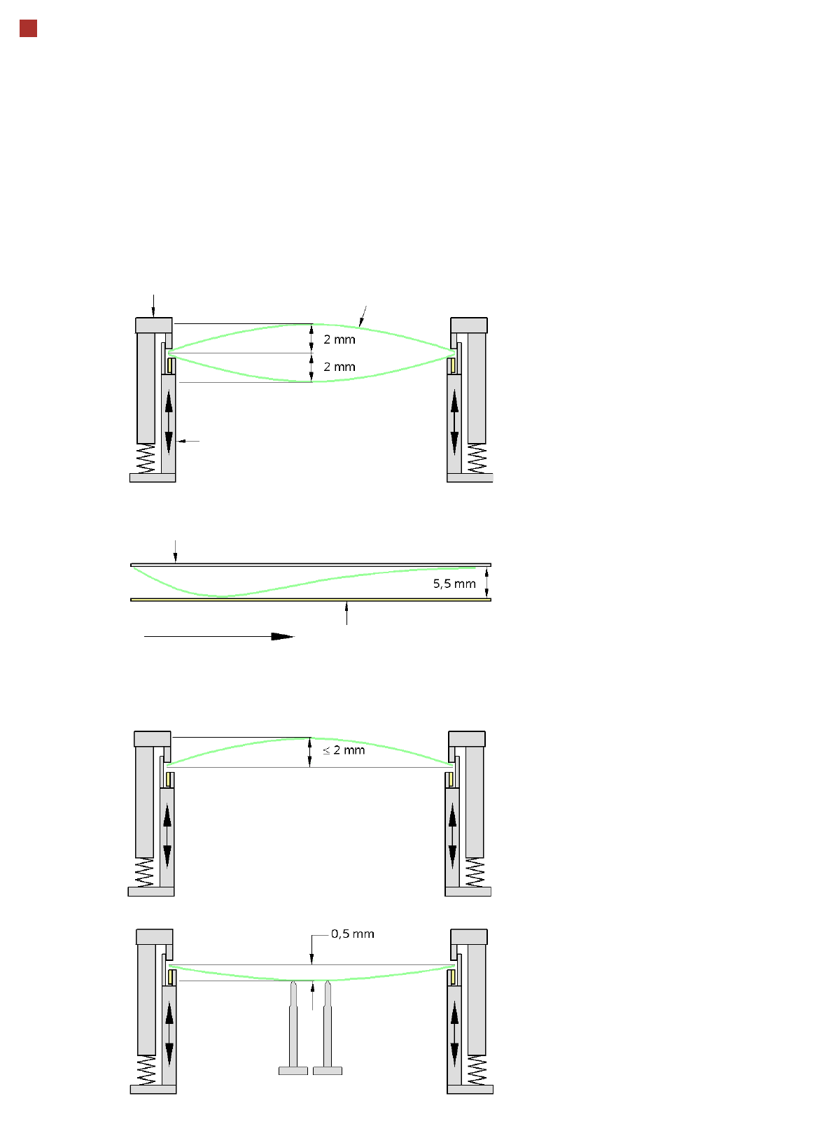
PCB warpage
PCB warpage across the direction of travel
max. 1 % of the PCB diagonal, but not
exceeding 2 mm
PCB warpage on the conveyor
PCB warpage during placement
PCB transport direction
PCB warpage downwards max. 0.5 mm
Use the magnetic pin supports, to achieve
this value.
Conveyor belt
Fixed clamped edge
PCB warpage in direction of travel
+ PCB thickness < 5.5 mm
Fixed clamped edge
Movable clamping device
When there is warpage under 2 mm, the
inkspots in the center of the board are also
within the focus of the digital camera. When
all the tolerances are taken into account,
this value is reduced to 1.5 mm.
You should also note that the warpage
reduces the component height.
Magnetic pin support
PCB
27
Smart Pin Support
General
Wide boards tend to deflect
during placement such that,
under certain circumstances,
the components can no lon-
ger be placed with the
desired accuracy. Highly
curved PCBs also affect the
placement accuracy. This
problem can be easily recti-
fied by fitting support pins on
the lifting table.
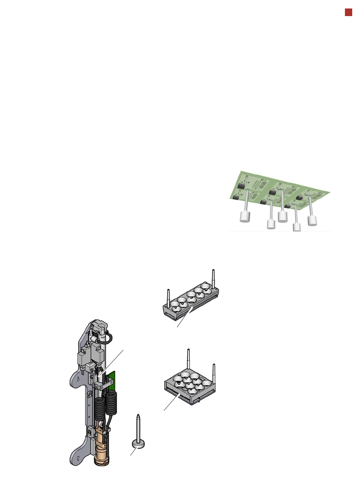
Smart Pin Support
The support pins are auto-
matically placed on the lifting
table with the help of the
Smart Pin Support option. A
gripper unit is used to pick
the support pins up from spe-
cial magazines and place
them in the prescribed posi-
tions.
Before you place a smart
support pin, the placement
area is cleaned from any
contaminants with a gentle
blast of air. In addition, the
correct position of the sup-
port pins is checked after
placement, with the PCB
camera.
Magazines
There are two different mag-
azines available for auto-
matic changeover to max. 10
support pins in the various
machine configurations.
These magazines are fixed
to a magazine holder and are
fitted to the component trol-
ley docking unit.
Programming
The positions of the support
pins in the machine can be
defined for each board side,
in the SIPLACE Pro Board
Editor.
A 3D diagram of the board
and support pins allows you
to detect and avoid potential
collisions with components,
even during stepped trans-
portation of extra long
boards.
Magazine L 10
Magazine Q 10
Gripper unit
Support pin
28
Component Provision SIPLACE SX1/SX2
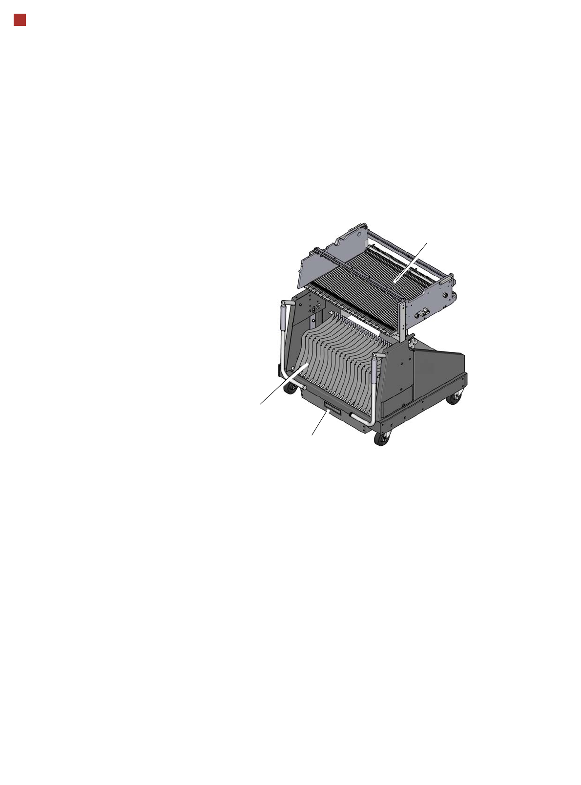
Component trolley
Component trolley
SIPLACE SX
The SIPLACE SX compo-
nent trolleys are independent
and easily maneuverable
modules. The SIPLACE SX
machines can accommodate
two component trolleys, each
with 60 tracks. If a WPC5/
WPC6 is set up at one of the
locations, the other location
can accommodate a compo-
nent trolley with 30 tracks.
The tape reels are taken up
into the tape container of the
component trolley. A cutting
device on the machine auto-
matically cuts the used tape
material. The component
trolleys can be set up directly
on the machine or at an
external setup area with
feeder modules. The benefits
of offline setup are that the
configurations can be pre-
pared without stopping the
line. This allows the setup to
be changed very quickly
using the changeover table
principle. The SIPLACE SX
component trolleys also sup-
port fast setting up and tear-
ing down of feeder modules
even during the placement
process.
The component feeders are
at rest during the placement
process - allowing tapes to
be spliced without stopping
the machine. With the help of
an optional component bar-
code reader and the Setup
Center option, the barcodes
on the tape reels can be read
and checked.
This ensures the correct
assignment of components
to tracks and the traceability
of PCB placement with the
Traceability software.
For safety reasons, unoccu-
pied locations are fitted with
so-called dummy feeder
modules.
Component trolley SIPLACE SX
Tape container
Waste container for remaining
empty tape
Changeover table