00192791-02.pdf - 第36页
2 Ceramic S ubstrate Centering Unit User Manual S IPLACE HS-50 2.2 Combination of Position Recognition and Mechanical Centering Software Version SR.502.xx 01/01 Issue 36 &RPEL QDWLRQRI3R VLWLR Q5HFRJQL WLRQDQ…

User Manual 2 Ceramic Substrate Centering Unit
Software Version SR.502.xx 01/01 Issue 2.1 Using the Option
35
&HUDPLF6XEVWUDWH&HQWHULQJ8QLW
8VLQJWKH2SWLRQ
The optional "mechanical ceramic substrate centering unit for HS-50" (see Section 2.3) is always
used in combination with position recognition of fiducials on the substrate.
This combination is mandatory to maintain the placement accuracy because, with the mechanical
ceramic substrate centering unit HS-50, the substrate is locked in the placement position horizon-
tally only and only in the X-direction (see Section 2.3.2). The tolerance of the position in the Y-
direction therefore depends on the tolerance of the set conveyor width relative to the width of the
current ceramic substrate.
The position of the fiducials is recognized either with the standard PCB camera with normal illu-
mination, with the optional oblique illumination or with the PCB camera multicolor.
Oblique illumination is not required, nor can it be used, when the PCB camera multicolor is utilized
for position recognition.
If the mechanical ceramic substrate centering station is used, it must always completely installed
and activated in all processing areas of a conveyor system.
On the other hand, the hardware for "mechanical ceramic substrate centering" is NOT to be in-
stalled on a machine with only position recognition (see CAUTION text in Section 2.3) and con-
veyor modules of the processing areas have to be equipped for PCB clamping unit (holddown for
PCB clamp) as described in the Service Manual.
NOTE:
Due to the limited space available, precision calibration is not possible if the mechanical ceramic
substrate centering unit is installed.

2 Ceramic Substrate Centering Unit User Manual SIPLACE HS-50
2.2 Combination of Position Recognition and Mechanical Centering Software Version SR.502.xx 01/01 Issue
36
&RPELQDWLRQRI3RVLWLRQ5HFRJQLWLRQDQG
0HFKDQLFDO&HQWHULQJ
For details regarding the possible combinations of the types of centering between Conveyor 1 and
Conveyor 2, see Section 2.8.
&HQWHULQJ6XEVWUDWHVRQ0DFKLQHVZLWK3&%&DPHUD 2EOLTXH,OOXPLQDWLRQ
The decision as to whether work will be performed with the PCB camera with normal illumination
(see User Manual, PCB Vision System) or with the optional oblique illumination (see Section 2.6)
depends on the design of the fiducials placed on the substrate.
&HQWHULQJRI&HUDPLF6XEVWUDWHVRQ0DFKLQHVZLWK3&%&DPHUD0XOWLFRORU
If the optional PCB camera multicolor has been installed in place of the PCB camera with normal
illumination, it can be used to acquire at least the entire range of fiducials currently recognized
with normal or oblique illumination (see single document "User Manual PCB Camera Multicolor"
Item no. 00192790-01).
Mechanical centering station Mechanical substrate centering AND position recognition of
substrates with PCB camera (normal illumination) or PCB
camera multicolor.
Mechanical and oblique illumi-
nation
Mechanical substrate centering AND position recognition of
substrates with optional oblique illumination of the PCB
camera.
-> Oblique illumination is always possible for both
conveyors.
User Manual 2 Ceramic Substrate Centering Unit
Software Version SR.502.xx 01/01 Issue 2.3 Mechanical Ceramic Substrate Centering
37
0HFKDQLFDO&HUDPLF6XEVWUDWH&H QWHULQJ
8VHDQG/RFDWLRQ
The optional "Mechanical ceramic substrate centering HS-50" is used to lock in X-direction of the
placement position, substrates with a width of 50 mm to 140 mm, with positional stability and care-
fully to protect the material. The ability to place the ceramic substrates all the way to the edge of
the substrate is a further advantage.
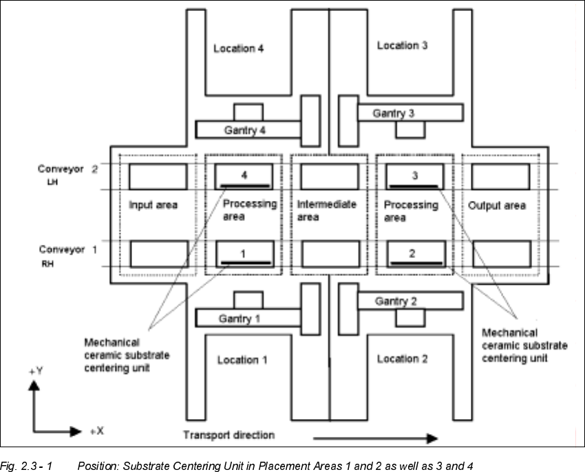
The mechanical ceramic substrate centering unit for the HS-50 is mounted in processing areas,
gantry 1 and 2 and/or 3 and 4 - next to the stationary side of the conveyor - on the pertinent lifting
table plate (see Fig. 2.3 - 1). Both processing areas of the pertinent conveyor have to be changed
over from PCB clamping to mechanical ceramic substrate centering (see Fig. 2.3 - 3).
If requested by a customer, the mechanical ceramic substrate centering unit can also be supplied
for "conveyor left".