00192791-02.pdf - 第41页
User Manual 2 Ceramic Substrate Centering Unit Software Version S R.502.xx 01/01 Issue 2.3 Mechanical Ceramic Substrate Centering 41 $GDSWLQJWRWKH6XEV WUDWH6 L]H The cer amic s ubstrate centeri ng un it is ad…
2 Ceramic Substrate Centering Unit User Manual SIPLACE HS-50
2.3 Mechanical Ceramic Substrate Centering Software Version SR.502.xx 01/01 Issue
40
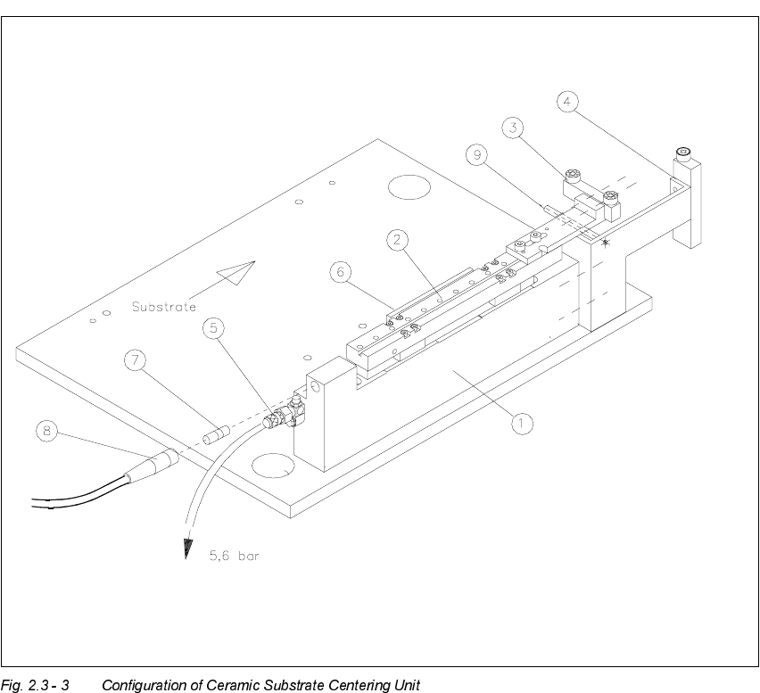
Key:
4. Body
5. X-slide unit
6. Stop rail 1, 2, or 3 (movable stop) with 2 ball bearings for 50 mm to 140 mm,
fastened with 2 socket head cap screws M3 x 8
7. Stop unit kit 1, 2 or 3 (fixed stop) with stationary roller of plastic AND distance bolt:
for 50 mm to 140 mm
8. Compressed air connection 5.6 bar / pneumatic hose
9. Flat cylinder and tension spring
10.Proximity switch
11.Proximity switch cable with plug-in connection
12.Distance bolt
User Manual 2 Ceramic Substrate Centering Unit
Software Version SR.502.xx 01/01 Issue 2.3 Mechanical Ceramic Substrate Centering
41
$GDSWLQJWRWKH6XEV WUDWH6 L]H
The ceramic substrate centering unit is adapted to the substrate size that is to be processed next
by installing the appropriate stop rail and the appropriate stop unit (Item no.: see table,
Fig. 2.3 - 4, below).
CAUTION
The distance bolt on the stop unit (kit 1, 2 or 3) WITH distance bolt is not to remove !
The following components (see also Fig. 2.3 - 5) are required for the adapting:
Designation For substrate width Item no.
Stop rail 1 assembly
with parallel pin
for 50 mm to 62 mm 00358877-01
Stop rail 2 assembly for > 62 mm to 106 mm 00358884-01
Stop rail 3 assembly for > 106 mm to 140 mm 00358885-01
Stop unit kit 1 (complete
with distance bolt)
for 50 mm to 62 mm 00358874-01
Stop unit kit 2 (complete
with distance bolt)
for > 62 mm to 106 mm 00358875-01
Stop unit kit 3 (complete
with distance bolt)
for > 106 mm to 140 mm 00358876-01
2 Ceramic Substrate Centering Unit User Manual SIPLACE HS-50
2.3 Mechanical Ceramic Substrate Centering Software Version SR.502.xx 01/01 Issue
42
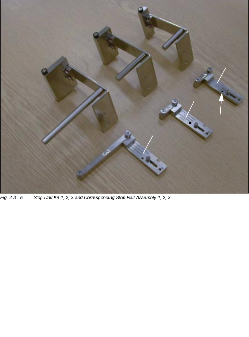
Key:
1. Stop unit Kit 1, fixed stop
2. Stop unit Kit 2, fixed stop
3. Stop unit Kit 2, fixed stop
4. Stop rail 1, 2 and 3, assembly (see marks
and
), movable stop
5. Parallel pin to limit the lift:
MUST be on stop rail 1.
NOTE:
Install the stop unit kit 1 (fixed stop) and stop rail "", assembly (= movable stop) for substrates
50mm to 62mm wide that are MORE than 50mm long (e. g., twice as long): See table,
Fig. 2.3 - 4, above and Fig. 2.3 - 5).