00192791-02.pdf - 第44页
2 Ceramic S ubstrate Centering Unit User Manual S IPLACE HS-50 2.3 Mechanical Ceramic Substrate Centering Software Version SR.502.xx 01/01 Issue 44 Å Ba ck out the screws fa stening th e stop uni t to the X-slide uni t…

User Manual 2 Ceramic Substrate Centering Unit
Software Version SR.502.xx 01/01 Issue 2.3 Mechanical Ceramic Substrate Centering
43
DANGER
Only the line engineer is permitted to perform the following work.
The safety instructions in the chapter "Operational Safety" in the User Manual HS-50 take prece-
dence.
BEFORE any work, the machine must be switched OFF and isolated from the mains.
In addition, the compressed air feed must be switched OFF at the main valve of the compressed
air unit in the machine frame.
While working, secure the machine conscientiously against other persons and against being re-
started without authority. Proceed as described in the chapter "Locking of the Machine".
Å The movable component changeover table remains moved into place and connected.
Å Turn the machine OFF as described in the above DANGER text.
Å The mechanical ceramic substrate centering unit is left installed during the adapting to the sub-
strate size.
Å Move the Y-gantry in such a manner that the ceramic substrate centering unit is readily acces-
sible.
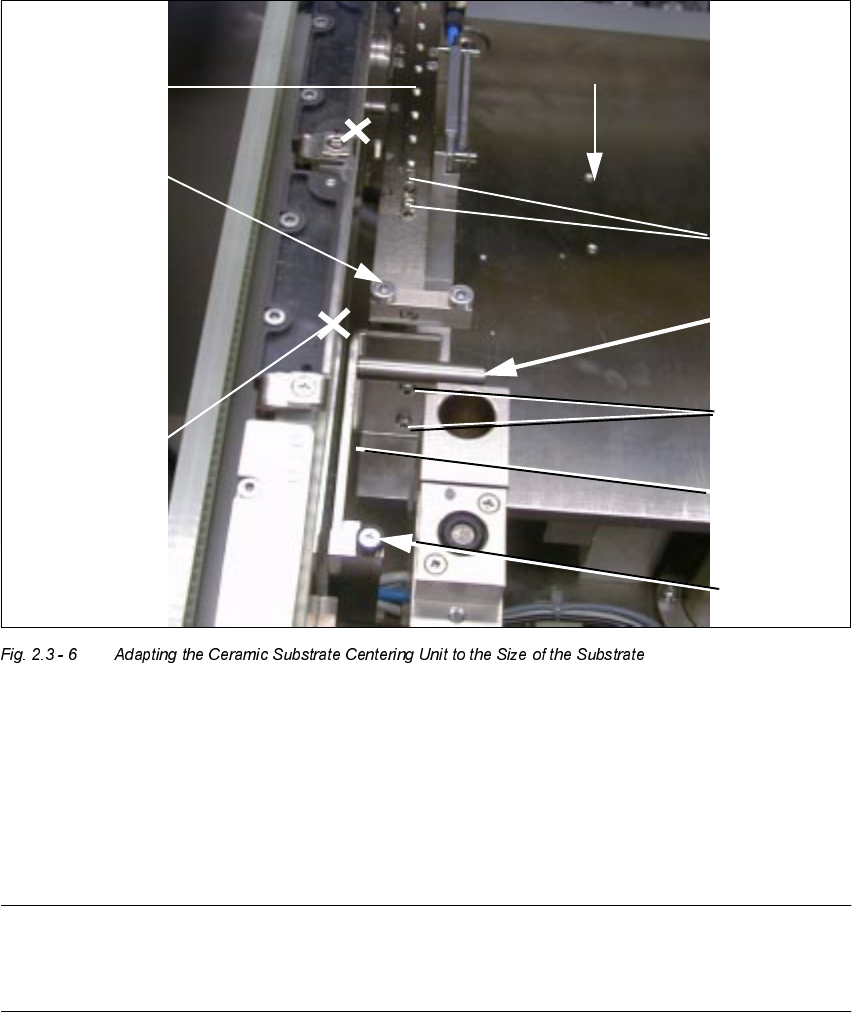
Å Loosen the screws fastening the stop rail to the X-slide unit (2 socket head hex cap screws M3:
see Fig. 2.3 - 6).
Å Install the stop rail required based on the substrate size (see table above).
2 Ceramic Substrate Centering Unit User Manual SIPLACE HS-50
2.3 Mechanical Ceramic Substrate Centering Software Version SR.502.xx 01/01 Issue
44
Å Back out the screws fastening the stop unit to the X-slide unit (2 socket hex had cap screws
M3).
Å Install the stop unit required for the particular substrate size (kit 1, 2 or 3, see table,
Fig. 2.3 - 4, above).
Å Turn ON the machine and the compressed air.
Å If necessary, conduct a test run with substrate (see Section 2.7).
NOTE:
If the substrate is lifted when the open centering unit moves upward, the LINE ENGINEER must
adjust the stopper position, as described in Section 2.3.7.
1RWHVRQ2SHUDWLRQ
The type of illumination of the position recognition (see Section 2.2) must correspond to the fidu-
cials on the substrate.This does not apply if a PCB camera multicolor is being used.
The operation during the placement run corresponds to the steps during PCB placement.
Roller
2 socket hex
head screws
Stop unit
with roller
Stop rail with
ball bearings
X-slide unit
(3 versions)
(3 versions)
M3 x 8
Connection
rail must be
removed!
Distance bolt
AND
distance bolt
7UDQVSRUWGLUHFWLRQ
2 socket hex
head screws
M3 x 8
User Manual 2 Ceramic Substrate Centering Unit
Software Version SR.502.xx 01/01 Issue 2.3 Mechanical Ceramic Substrate Centering
45
Using the single function "Ceramic substrate centering" in the conveyor menu it is possible to open
and close the mechanical substrate centering unit for test purposes (see Section 2.7.1).
After placing a substrate in the input conveyor, it is possible to conduct a substrate trial run as de-
scribed in Section 2.7.1 using the "Single functions" of the processing conveyor.
(UURU0HVVDJHV3RVVLEOH&DXVHVDQG5HPHG\
In case of raising the substrate during the centering process -> see Section 2.3.7.
In the event of an error, one of the following error messages is output at the station’s operator in-
terface:
– "Error, ceramic substrate centering 1" or
– "Error, ceramic substrate centering 2"
This stops the placement process.
The messages mean that the required condition of the mechanical substrate centering unit "open"
/ "closed"), which is interrogated by the proximity switch of the substrate centering unit, is absent.
Addition
means: The error is in processing area 1 or 4 (see Fig. 2.3 - 1).
Addition
means: The error is in processing area 2 or 3 (see Fig. 2.3 - 1).
Possible causes:
– There is a mechanical obstruction,
e.g., due to a component that is wedged in place and is preventing the X-slide from moving:
Å Remove the wedged component with a vacuum cleaner or, if necessary, with tweezers as
described under "Weekly Maintenance" in the Section 2.4.
– Ther is a malfunction at the tension spring on the flat cylinder:
Å Remedy the malfunction as described under "Monthly Maintenance" in Section 2.5.
– There is another malfunction:
Defect of the proximity switch / solenoid valve / leaky pneumatic connection, not plugged in
properly, cable conductors broken.
Å Notify the line engineer / service technician.