00192791-02.pdf - 第49页
User Manual 2 Ceramic Substrate Centering Unit Software Version S R.502.xx 01/01 Issue 2.3 Mechanical Ceramic Substrate Centering 49 &KDQJHIURP&HUDPLF6 XEVWUDW H&H QWHULQJWR3&%&OD PSLQJ O…
2 Ceramic Substrate Centering Unit User Manual SIPLACE HS-50
2.3 Mechanical Ceramic Substrate Centering Software Version SR.502.xx 01/01 Issue
48
Key to 2.3 - 7, continued:
1. Stopper axles (on dual conveyor: continuous axles for belt 2)
2. Stopper assembly
3. Connection rail on fixed and movable side of the conveyor
4. Fastening for the connection rails: 2 socket hex head cap screws M4
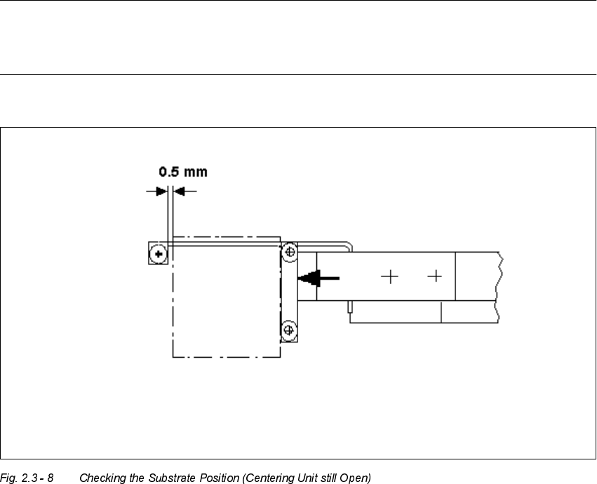
NOTE:
As shown below, the substrate edge pointing toward the unloader must still be 0.5 mm IN FRONT
OF that of the unmovable roller of the fixed stop while the centering unit is open.
Å In processing area 1 loosen the screws fastening the connection rail on inside left and inside
right of the conveyor assemblies (2 socket hex head cap screws M 4 each).
Å Move the connection rails (incl. guide axles and stopper) the required diistance in PARALLEL
in the direction of the ceramic substrate centering unit and retighten the screws to fasten the
connection rails in this position.
Å Conduct a trial placement with substrate and check whether the substrate can be centered.
User Manual 2 Ceramic Substrate Centering Unit
Software Version SR.502.xx 01/01 Issue 2.3 Mechanical Ceramic Substrate Centering
49
&KDQJHIURP&HUDPLF6 XEVWUDW H&H QWHULQJWR3&%&OD PSLQJ
Only the service engineer is permitted to do the reinstallation and must do so on the basis of the
Service Manual or the Retrofitting Manual.
For this purpose the mechanical ceramic substrate centering units of the two processing areas of
the pertinent conveyor must be isolated electrically and pneumatically and then disassembled.
The connection rails from the retrofit kit must be installed on the pertinent conveyor assemblies.
2 Ceramic Substrate Centering Unit User Manual SIPLACE HS-50
2.4 Weekly Maintenance Software Version SR.502.xx 01/01 Issue
50
:HHNO\0DLQWHQDQFH
DANGER
In addition to these instructions, you will always need the current edition of the "Maintenance Man-
ual for HS-50", Item no. 00191375-02, to restore the machine to its original safe condition in terms
of maintenance and to perform all of other the jobs specified for this maintenance period.
During all maintenance work, comply with the safety instructions in Chapter 1 of the above-men-
tioned "Maintenance Manual for HS-50". It also contains the explanation for the symbols used.
Perform the maintenance work described while conducting the "Vacuuming Off the PCB Con-
veyor" described below during the weekly maintenance work on the "Mechanical Ceramic Center-
ing Unit".
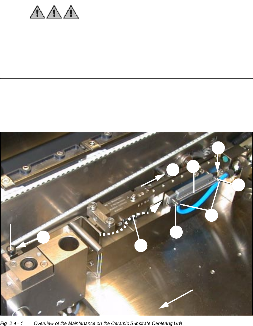
The maintenance must be performed on ALL of existing centering units (see Fig. 2.3 - 1).
7UDQVSRUWGLUHFWLRQ
0[
6WRSXQLW