00192791-02.pdf - 第53页
User Manual 2 Ceramic Substrate Centering Unit Software Vers ion SR.502.xx 01/01 Iss ue 2.5 Monthly Maintenance 53 0RQWKO\0DLQWHQDQFH DANGER In additi on to th ese inst ruction s, you wi ll always need th e current …

2 Ceramic Substrate Centering Unit User Manual SIPLACE HS-50
2.4 Weekly Maintenance Software Version SR.502.xx 01/01 Issue
52
&KHFNLQJWK H5ROOHUR QW KH ) L[HG6WRS
Å Check to see if there is any damage to the surface (contact area of substrate) of the stationary
roller of the fixed stop (see Fig. 2.4 - 1 -> Pos. 4).
Å If there is an error, unscrew the screw fastening the roller (1 cross-slotted screw M3 x 8 DIN
965).
Å If the circumference of the roller is still in satisfactory condition, turn the roller,
until the satisfactory surface is pointing toward the substrate, then tighten the cross-slotted
screw M3 x 8 to fasten the roller.
Å If the roller no longer has a satisfactory surface, use the cross-slotted screw M3 x 8 to fasten
the new roller ,Item no. 00347284-01, in place.
&KHFNLQJWKH7HQVLRQ6SULQJ
If the tension spring on the flat cylinder of the mechanical ceramic substrate centering unit is faulty
or is mounted incorrectly, this may result in an error message accompanied by the stoppage of the
placement run -> Proximity switch signal for "Centering unit open" is not issued.
Å Check whether the open ceramic substrate centering unit is still being held securely at the end
stop (= maximum "open" position) by the tension spring (see Fig. 2.4 - 1 -> Pos. 5).
Å If applicable, suspend both ends of the spring correctly or, if the tension spring is damaged,
install a new one as follows:
Å Use the Seeger circlip pliers to remove the grip ring (see Fig. 2.4 - 1 -> Pos. 6) from the
spring suspension pin.
Å Unhook the faulty spring at both ends.
Å Suspend the new tension spring, Item no. 00359769-01 from both ends and install the cir-
clip (new, if applicable), Item no. 00048315-01 on the spring suspension pin.

User Manual 2 Ceramic Substrate Centering Unit
Software Version SR.502.xx 01/01 Issue 2.5 Monthly Maintenance
53
0RQWKO\0DLQWHQDQFH
DANGER
In addition to these instructions, you will always need the current edition of the "Maintenance Man-
ual for HS-50", Item no. 00191375-02, to restore the machine to its original safe condition in terms
of maintenance and to perform all of other the jobs specified for this maintenance period.
During all maintenance work, comply with the safety instructions in Chapter 1 of the above-men-
tioned "Maintenance Manual for HS-50". It also contains the explanation for the symbols used.
Perform the maintenance work described while conducting the "Vacuuming Off the PCB Con-
veyor" described below during the monthly maintenance work on the "Mechanical Ceramic Cen-
tering Unit".
The maintenance must be performed on ALL of existing centering units (see Fig. 2.3 - 1).
([SHQGDEOH0DWHULDOV
For the monthly maintenance you need:
– SIPLACE cleaning cloth, Item no. 00315253-01
3UHSDUDWRU\ 6WHSV
Å Establish the maintenance condition of the machine and the accessibility of the work area.
Proceed as described for the cleaning of the PCB conveyor in the section "Weekly Mainte-
nance", in the "Maintenance Manual for HS-50".
&OHDQLQJDQG$SSO\LQJ3 UHVHUYDWLYHWR6OLGH*XLGH
Å Clean the entire length of the contact surfaces of the slide guide for the ceramic substrate cen-
tering unit with a new SIPLACE cleaning cloth. This simultaneously applies a thin coat of oil to
the contact surfaces.
2 Ceramic Substrate Centering Unit User Manual SIPLACE HS-50
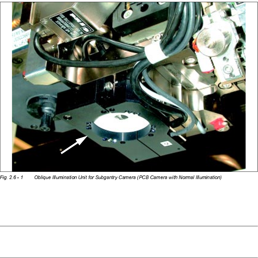
2.6 Utilizing Oblique lllumination to Recognize the Position of a Fiducial Software Version SR.502.xx 01/01 Issue
54
8WLOL]LQJ2EOLTXHOOOXPLQDWLRQWR5HFRJQL]HWKH
3RVLWLRQRID)LGXFLDO
*HQHUDO,QIRUPDWLRQ
The particular features of the ceramic substrate must be taken into consideration when trying to
recognize the position of fiducials on ceramic substrates. The contrast depends very highly on
the properties of the surface the fiducials are on, just how unobstructed area around the fiducial
is, and the type of illumination selected.
The optional oblique illumination unit is located on the front of the subgantry PCB camera.
As an alternative to the existing illumination of the subgantry PCB camera with normal illumina-
tion, you can switch ON this oblique illumination (see table in Section 2.2 and Section 2.6).
NOTE:
The oblique illumination can only be used on the subgantry PCB camera (with normal illumina-
tion).