OM-1058-002.pdf - 第102页
Tg0409-PM-SO 9.6 Strength of Carrier and Cover T apes 9.6 Strength of Carrier and Cover T apes Carrier T ape When a tensile force of 10 N (1.02 kgf) is applied in the direction of unreeling the tape, the tape shall withs…
Tg0409-PM-SO
9.3 Leader Section (Tape End Section)
9.3 Leader Section (Tape End Section)
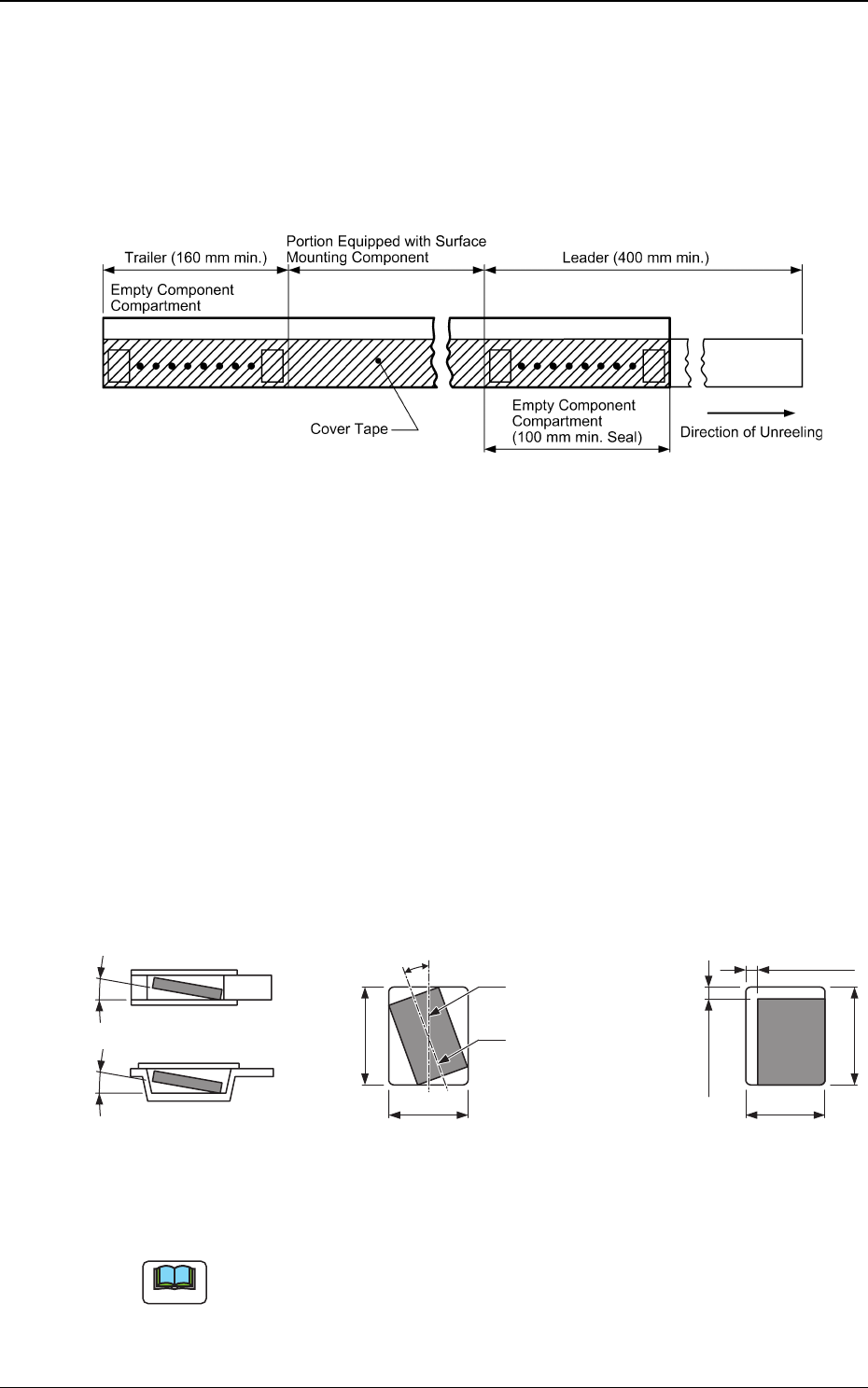
The tape length in the leader section should be 400 mm or more including
the empty component compartment.
Such empty component compartment should be sealed with a cover tape for
100 mm or more.
Fig. 113
Fig. 114
9.4 Trailer Section (Tape Tailer Section)
The tape length of the trailer section should be 160 mm or more including
the empty component compartment.
The empty component compartment should be sealed with a cover tape.
The last portion of carrier tape shall release from the reel hub.
9.5 Position of Taped Component
0410-002 100
Keep a clearance around the component such that the direction of the
component is not changed in the punched section or within the em-
bossed section and so that it can easily be picked up from the punched
section or within the embossed section.
Note
(Note)
0.5 mm Max.
(Note)
0.5 mm Max.
Top View
Component Bias in
Horizontal Direction
B
0
A
0
Center Line of
Component Compartment
Center Line of
Component
(Note)
20 Max.
Top View
Component Revolution in
Horizontal Direction
Side Sectional View or
Front Sectional View
Component Inclination
10 Max.10 Max.
B0
A
0
Tg0409-PM-SO
9.6 Strength of Carrier and Cover Tapes
9.6 Strength of Carrier and Cover Tapes
Carrier Tape
When a tensile force of 10 N (1.02 kgf) is applied in the direction of
unreeling the tape, the tape shall withstand this force.
Cover Tape
When a tensile force of 10 N (1.02 kgf) is applied to the tape, the tape
shall withstand this force.
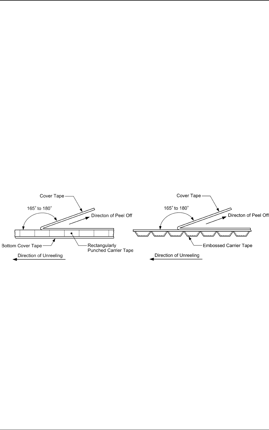
9.7 Peel Strength of Cover Tape
The direction of the cover tape peeling force should be maintained at an
angle of 165 to 180 degrees.
When the cover tape is peeled off at the speed of 300 mm/min +/- 10 mm/
min, the cover tape peeling force should be 0.1 to 0.7 N (10.2 to 71.4 gf).
Fig. 115 Angle in Peel Test Fig. 116 Angle in Peel Test
Rectangle Hole Punched
Carrier Type Taping
Embossed Carrier Type Taping
0410-002 101
Tg0409-PM-SO
9.8 Minimum Bending Radius
0410-002 102
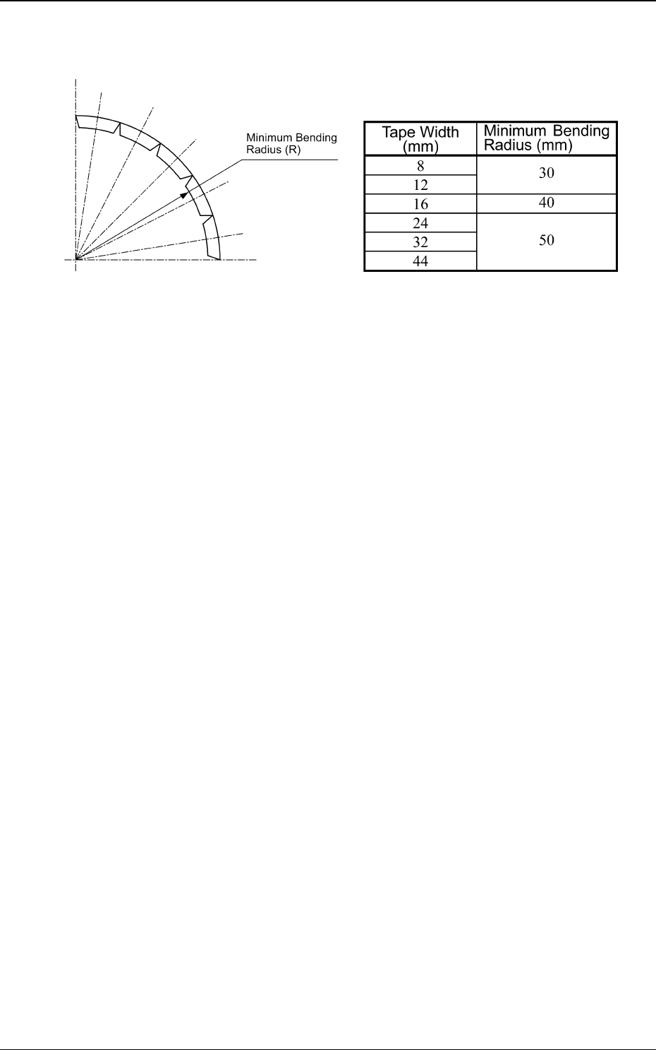
9.8 Minimum Bending Radius
Fig. 117 Minimum Bending Radius
When the tape is bent with the minimum bending radius, the tape shall not
be damaged, the components ahall maintain their position and direction in
the tape and shall be free from abnormalities such as damage.
Tape Width and Minimum Bending Radius
Table 30