OM-1058-002.pdf - 第11页
Tg0409-PM-SO 0410-002 10 2.1 Attachment of T apes Fig. 9 Foreign Substance on the Chute (5) Make sure there is no foreign substance sticking on the chute section or the rear side of the suppressor . If dirty , clean it. …
Tg0409-PM-SO
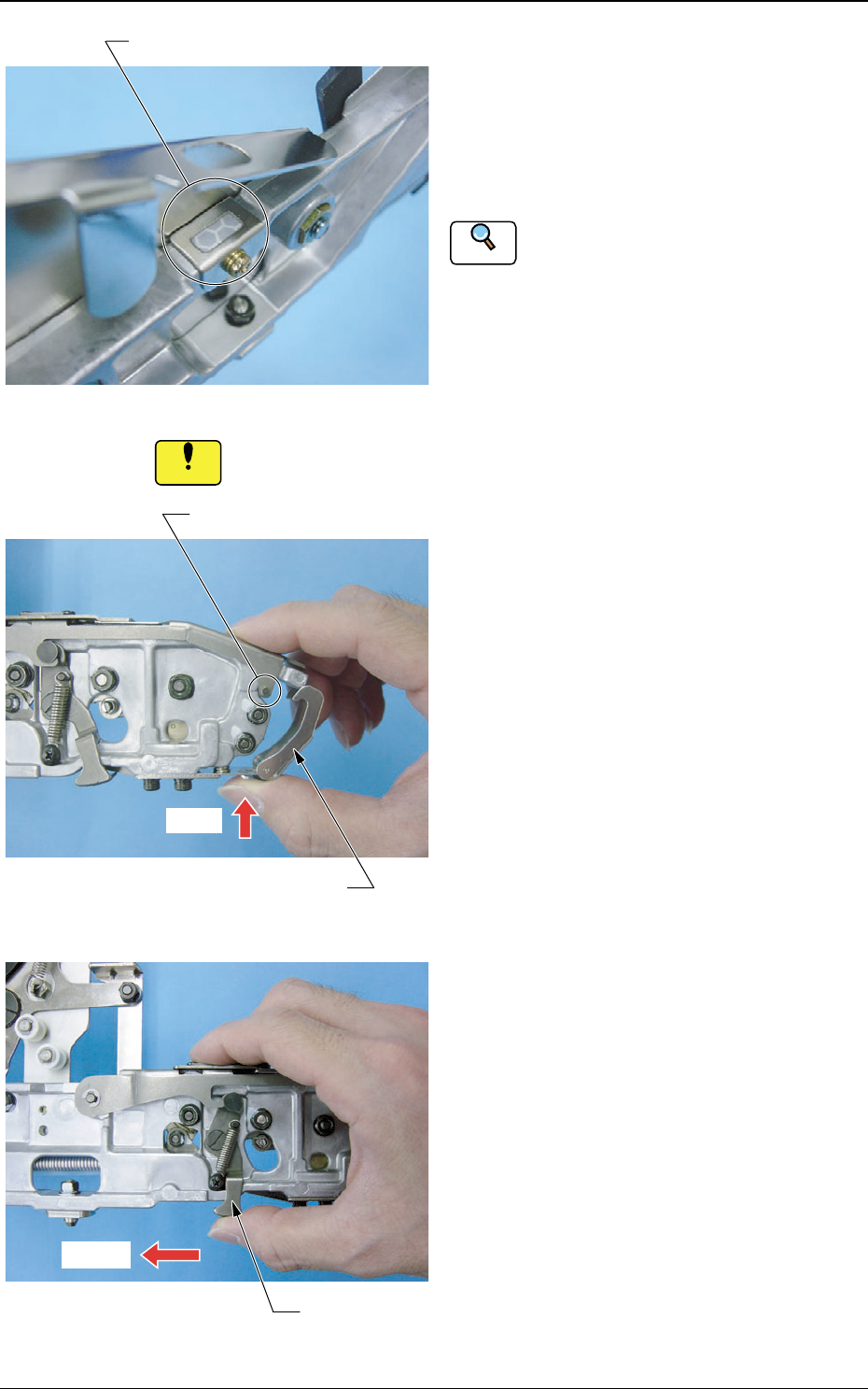
Fig. 6 Tape End Detection Reflector
(2) Make sure there is no dirt on the tape
end detection reflector.
Clean any adhered foreign substance, using
air-blow or brush.
Refer to "5.3.2 Maintenance in Tape Attach-
ment and Product Change" for details of
cleaning.
If there is any dirt on the tape end detection reflector, the tape
end might not be detected.
0410-002 9
2.1 Attachment of Tapes
Reference
(4) Detach the suppressor holding lever
from the suppressor hook section.
At that time, slide the suppressor holding
lever while pressing on its lower part.
Fig. 7 Detachment of Front Hook
(3) Detach the front hook from the pin.
At that time, slide the hook while pushing
the lower part of the hook.
Fig. 8 Detachment of Suppressor Holding Lever
Pin
Front Hook
Press
Suppressor Holding Leve
r
Slide it
Tape End Detection Reflector
Notice
Tg0409-PM-SO0410-002 10
2.1 Attachment of Tapes
Fig. 9 Foreign Substance on the Chute
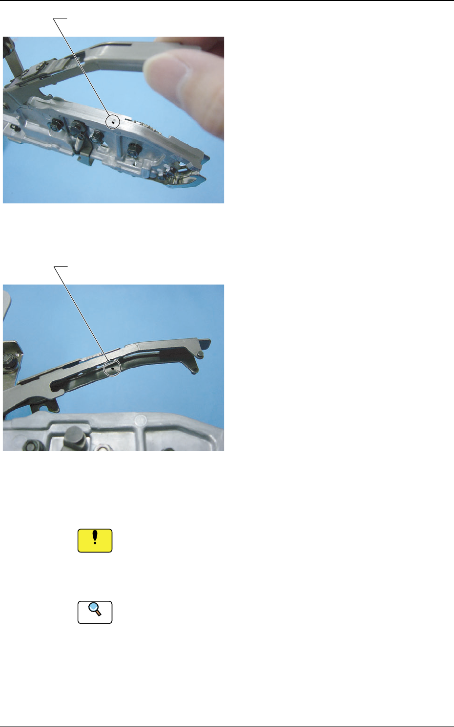
(5) Make sure there is no foreign substance
sticking on the chute section or the rear
side of the suppressor.
If dirty, clean it.
If there is any foreign substance (such as chip component or
dust) on the chute and rear surface of the suppressor when the
tape is attached, then it might cause a suppressor distortion or
pick-up error.
Refer to "5.3.2 Maintenance in Tape Attachment and Product Change"
for details of cleaning.
Reference
Chip Component
Chip Component
Notice
Fig. 10 Foreign Substance on the Rear
Surface of the Suppressor
Tg0409-PM-SO
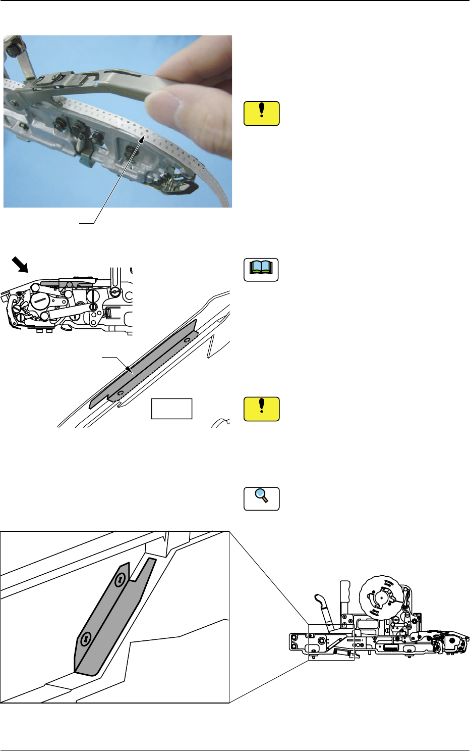
If a thin tape is being used in TF-1210, the
tape might come away from the chute
section. If so, mount the attached auxiliary
chute onto the chute section. Attach and
store the chute not to be used into the
housing tap, using set screws in order not
to lose. (Refer to Fig. 13).
If the set screws are fastened with
excessive torque in attaching to the
auxiliary chute, the screw sections
might become damaged.
Refer to "8.3 Specifications of 12 mm
Tape Feeder (For Embossed Tape) " for
Specifications of Tape.
0410-002 11
Fig. 11
Fig. 13 Housing Tap General View
(6) Lift the suppressor and then pass the
tape taken from the reel through the
suppressor.
Do not allow excessive loads on the
upper section when lifting the suppres-
sor, because the suppressor might
become deformed.
2.1 Attachment of Tapes
Tape
4
2
1
Auxiliary Chute
View
Fig. 12 Auxiliary Chute Attachment Position
General View
Notice
Notice
Reference
Note
TOP TAPE
MADE
IN
JAPAN
4
4
,
8
4
8
1
2
,
2
1
غغغغ-٤٤٤٤٤٤
Tape Feeder of TF-1610