OM-1058-002.pdf - 第13页
Tg0409-PM-SO 0410-002 12 2.1 Attachment of T apes Suppressor Stopper Pin If a thin tape of less than 0.3 mm thickness is used in a tape feeder of 16 mm width (TF- 1610), then replace the standard suppressor stopper pin w…
Tg0409-PM-SO
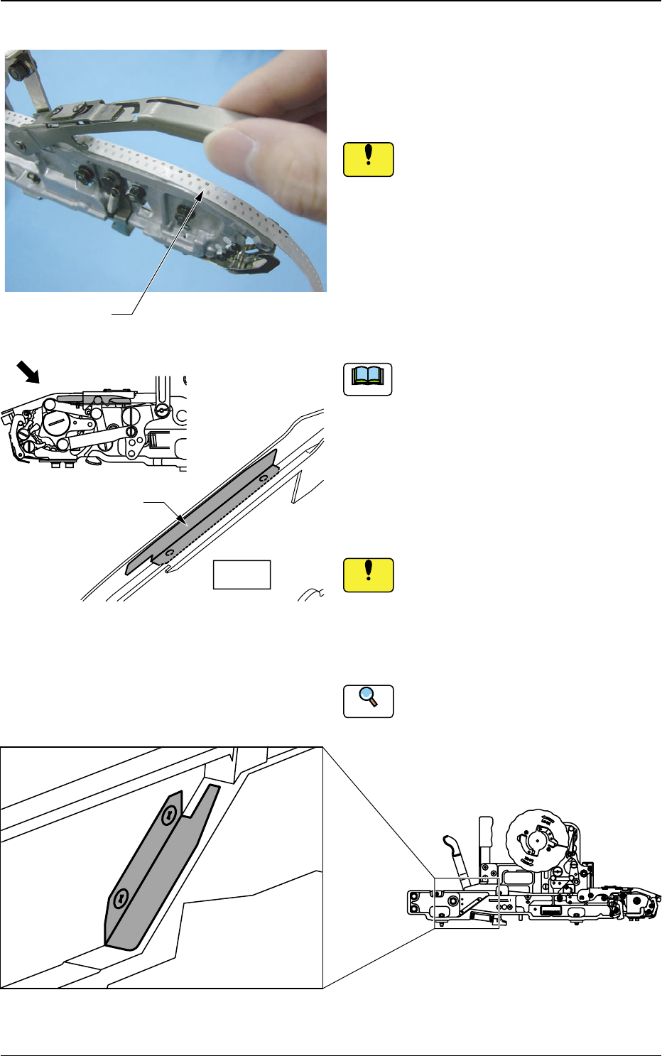
If a thin tape is being used in TF-1210, the
tape might come away from the chute
section. If so, mount the attached auxiliary
chute onto the chute section. Attach and
store the chute not to be used into the
housing tap, using set screws in order not
to lose. (Refer to Fig. 13).
If the set screws are fastened with
excessive torque in attaching to the
auxiliary chute, the screw sections
might become damaged.
Refer to "8.3 Specifications of 12 mm
Tape Feeder (For Embossed Tape) " for
Specifications of Tape.
0410-002 11
Fig. 11
Fig. 13 Housing Tap General View
(6) Lift the suppressor and then pass the
tape taken from the reel through the
suppressor.
Do not allow excessive loads on the
upper section when lifting the suppres-
sor, because the suppressor might
become deformed.
2.1 Attachment of Tapes
Tape
4
2
1
Auxiliary Chute
View
Fig. 12 Auxiliary Chute Attachment Position
General View
Notice
Notice
Reference
Note
TOP TAPE
MADE
IN
JAPAN
4
4
,
8
4
8
1
2
,
2
1
غغغغ-٤٤٤٤٤٤
Tape Feeder of TF-1610
Tg0409-PM-SO0410-002 12
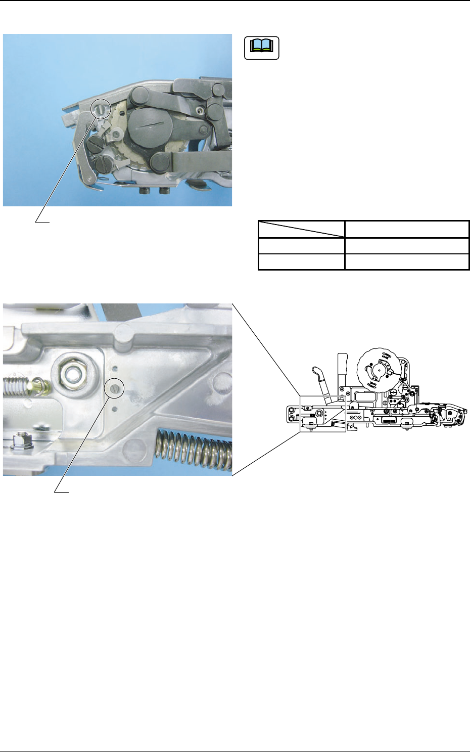
2.1 Attachment of Tapes
Suppressor Stopper Pin
If a thin tape of less than 0.3 mm thickness
is used in a tape feeder of 16 mm width (TF-
1610), then replace the standard suppressor
stopper pin with the attached suppressor
stopper pin for thin tapes. Attach and store
the unused suppressor stopper pin into the
housing tap in order not to lose it.
If any tape feeding error or pick-up error
occurs, replace it with a standard suppressor
stopper pin.
Table 2
Standard
For Thin Tape
Diameter
φ 4.1 mm
φ 3.5 mm
Fig. 14
Fig. 15
Note
Suppressor Stopper Pin Housing Tap
غغغغ-٤٤٤٤٤٤
TOP TAPE
MADE
IN
JAPAN
8
1
2
6
1
8
1
2
,
1
6
,
2
1
6
1
4
4
4
8
,
Tape Feeder of TF-1610
Tg0409-PM-SO
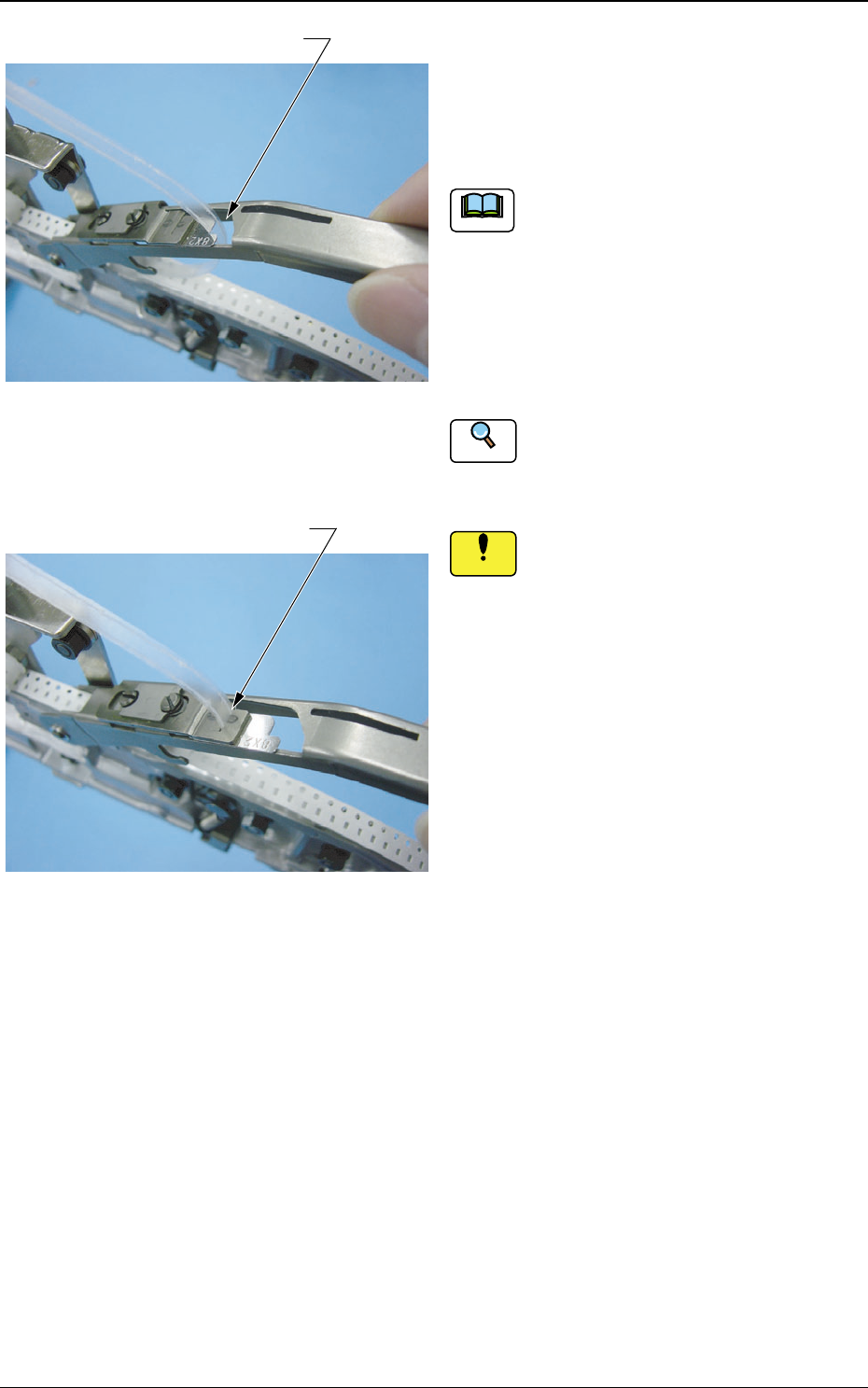
(7) Pass the cover tape through the cover
tape hole and then pass it through the
slit on the tape peeling section.
Make sure that there is no foreign substance
on the tape peeling section on the shutter
assembly. If there is any, clean it.
Also make sure that there is no dust or fiber
on the cover tape.
If there is any, remove it with a rag or air
gun.
Refer to "5.3.2 Maintenance in Tape Attach-
ment and Product Change", for cleaning the
tape peeling section on the shutter assembly.
Clean the tape peeling section on the
shutter assembly.
If any foreign substance (component or
dust) is on the tape peeling section
when the cover tape is attached, it might
cause a component deformation or pick-
up error.
Reference
0410-002 13
2.1 Attachment of Tapes
Cover Tape Hole
Slit
Fig. 16
Fig. 17
Notice
Note