OM-1058-002.pdf - 第14页
Tg0409-PM-SO (7) Pass the cover tape through the cover tape hole and then pass it through the slit on the tape peeling section. Make sure that there is no foreign substance on the tape peeling section on the shutter asse…
Tg0409-PM-SO0410-002 12
2.1 Attachment of Tapes
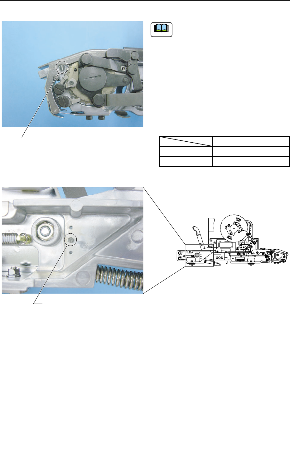
Suppressor Stopper Pin
If a thin tape of less than 0.3 mm thickness
is used in a tape feeder of 16 mm width (TF-
1610), then replace the standard suppressor
stopper pin with the attached suppressor
stopper pin for thin tapes. Attach and store
the unused suppressor stopper pin into the
housing tap in order not to lose it.
If any tape feeding error or pick-up error
occurs, replace it with a standard suppressor
stopper pin.
Table 2
Standard
For Thin Tape
Diameter
φ 4.1 mm
φ 3.5 mm
Fig. 14
Fig. 15
Note
Suppressor Stopper Pin Housing Tap
غغغغ-٤٤٤٤٤٤
TOP TAPE
MADE
IN
JAPAN
8
1
2
6
1
8
1
2
,
1
6
,
2
1
6
1
4
4
4
8
,
Tape Feeder of TF-1610
Tg0409-PM-SO
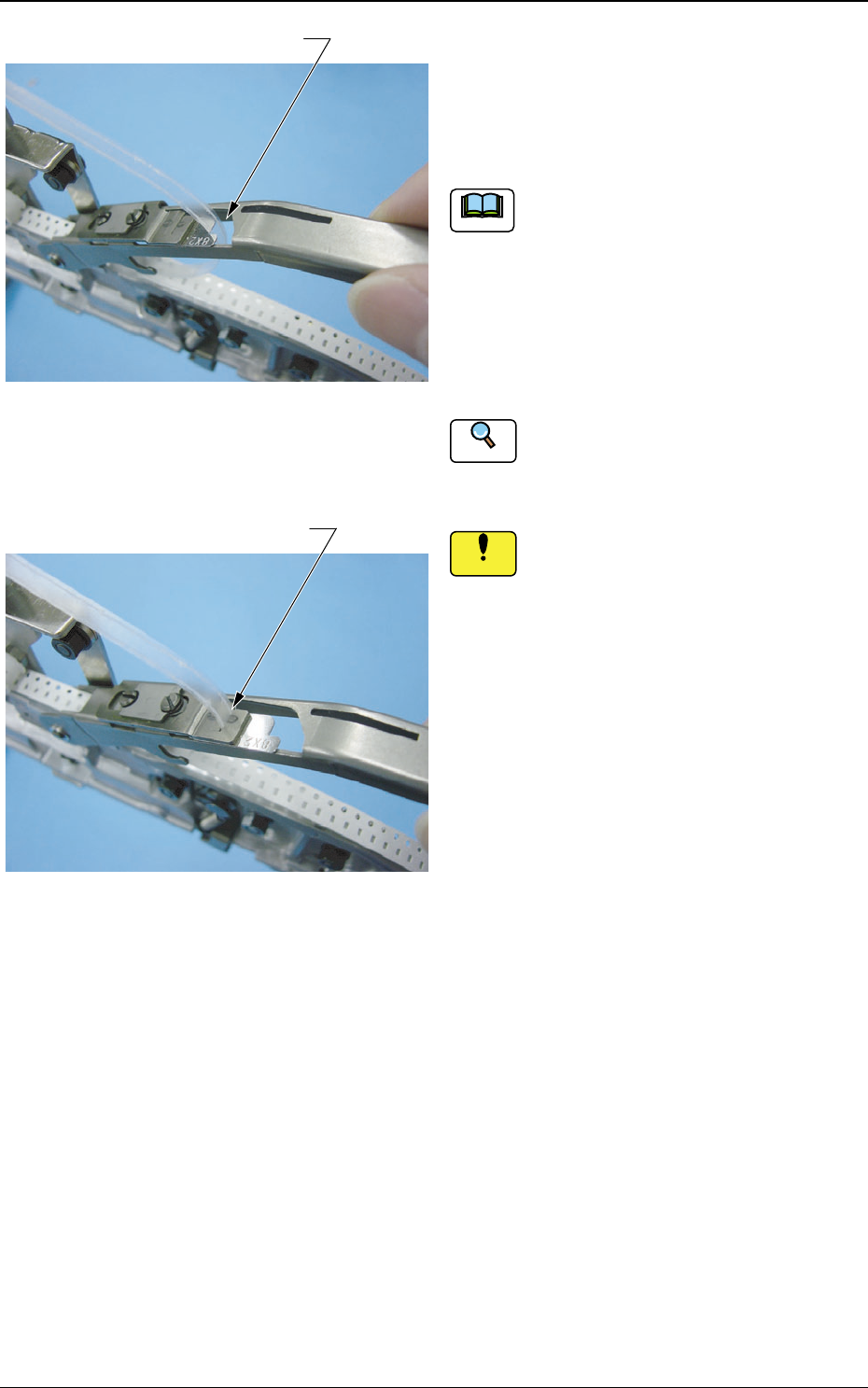
(7) Pass the cover tape through the cover
tape hole and then pass it through the
slit on the tape peeling section.
Make sure that there is no foreign substance
on the tape peeling section on the shutter
assembly. If there is any, clean it.
Also make sure that there is no dust or fiber
on the cover tape.
If there is any, remove it with a rag or air
gun.
Refer to "5.3.2 Maintenance in Tape Attach-
ment and Product Change", for cleaning the
tape peeling section on the shutter assembly.
Clean the tape peeling section on the
shutter assembly.
If any foreign substance (component or
dust) is on the tape peeling section
when the cover tape is attached, it might
cause a component deformation or pick-
up error.
Reference
0410-002 13
2.1 Attachment of Tapes
Cover Tape Hole
Slit
Fig. 16
Fig. 17
Notice
Note
Tg0409-PM-SO0410-002 14
Fig. 18
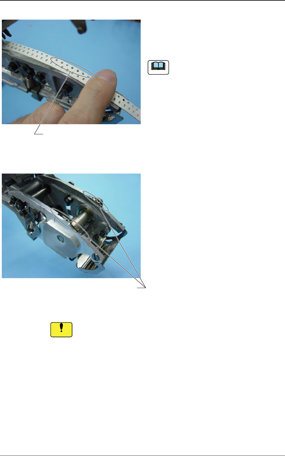
(8) Set the carrier tape so that the sprocket
pins are securely engaged with the
sprocket holes.
(a) Make sure there is no foreign substance
on the carrier tape.
If there is any, remove it with a rag or
air gun.
(b) For tape feeder of 32 or 44 mm width,
attach the tape, aligning it with the pins
on the sprockets on the right and left.
(Refer to Fig. 19).
2.1 Attachment of Tapes
If any foreign substance (chip component, dust, debris or fiber) is
left on the carrier tape then a pick-up error might be caused.
Pin
Fig. 19 Tape Feeder of 32 or 44 mm Width
Pin
Notice
Note