OM-1058-002.pdf - 第17页
Tg0409-PM-SO 0410-002 16 (12) Attach the suppressor holding lever to the suppressor hook section. Slide the suppressor holding lever by press- ing its lower section. 2.1 Attachment of T apes Fig. 22 Attachment of Front H…
Tg0409-PM-SO0410-002 15
2.1 Attachment of Tapes
Fig. 21
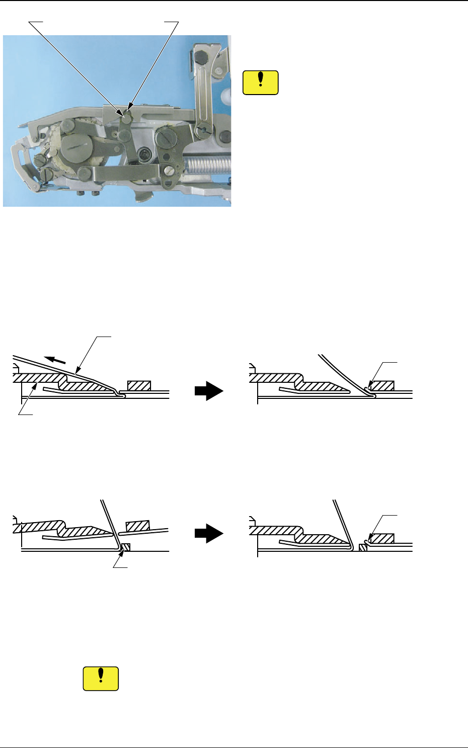
If the cover tape or the chip component gets caught by the
suppressor, then the peeling section might be deformed or a pick-
up error occur.
If there is any such catching of the cover tape or chip component,
do not pull it out forcibly; just lift the suppressor.
(10) Make sure that the cover tape or chip
component is not caught in the peeling
section.
If operation is performed with the
cover tape caught in the
suppressor . . .
It might also cause distortion in the tape
peeling section, or scratches on the cover
tape, which might lead to the tape's being
cut off.
The peeling section might be
deformed.
Suppressor
If the suppressor is lowered with
any foreign substance on the tape
surface . . .
Foreign Substance
Deformation
Deformation
Cover Tape
Notice
(9) Lower the suppressor carefully.
When the suppressor for the tape feeder
with a tape width of 12 mm or more is to
be set, if such suppressor is forced into
setting while the pin is not aligned with
the U-groove, the suppressor might be
deformed.
Always set the suppressor while the pin
is aligned with the U-groove.
Notice
U-GroovePin
Fig. 20
Tg0409-PM-SO0410-002 16
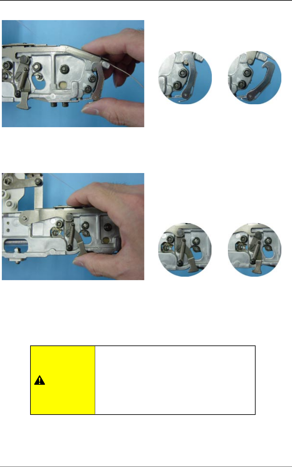
(12) Attach the suppressor holding lever to
the suppressor hook section.
Slide the suppressor holding lever by press-
ing its lower section.
2.1 Attachment of Tapes
Fig. 22 Attachment of Front Hook
(11) Catch the pin with the front hook.
Slide the hook by pressing its lower section.
Fig. 24 Attachment of Suppressor
Holding Lever
OK NG
Fig. 23 Front Hook Attachment Condition
OK NG
Fig. 25 Suppressor Holding Lever
Attachment Condition (Opposite
Side)
If the tape feeder is used when the front hook and
the suppressor holding lever have come off, the
machine might be damaged or a pick-up error
occur.
Attach the front hook and the suppressor holding lever
correctly.
CAUTION
Tg0409-PM-SO0410-002 17
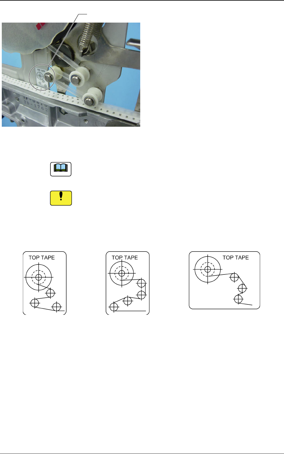
Fig. 26 Attachement of Cover Tape
(13) Set the cover tape on the take-up reel
socket through the roller according to
the instruction label.
2.1 Attachment of Tapes
Fig. 27
Instruction Label
The instruction label is attached to each tape feeder.
If the cover tape is taken up incorrectly, it might cause a take-up
error or feeding error.
• Instruction Label Enlarged View
Tape Feeder of 8 mm Width TF-0814 Tape Feeders of 12 mm Width or more
(except for TF-0814)
Notice
Note