OM-1058-002.pdf - 第24页
Tg0409-PM-SO 0410-002 23 2.3 Component Pick-up Position Alignment Component Center and Component Center Set Position for TF-441 1 (In the case of tape feeds of 24 mm pitch) The set position varies with the pitch. T wo or…
Tg0409-PM-SO0410-002 22
2.3 Component Pick-up Position Alignment
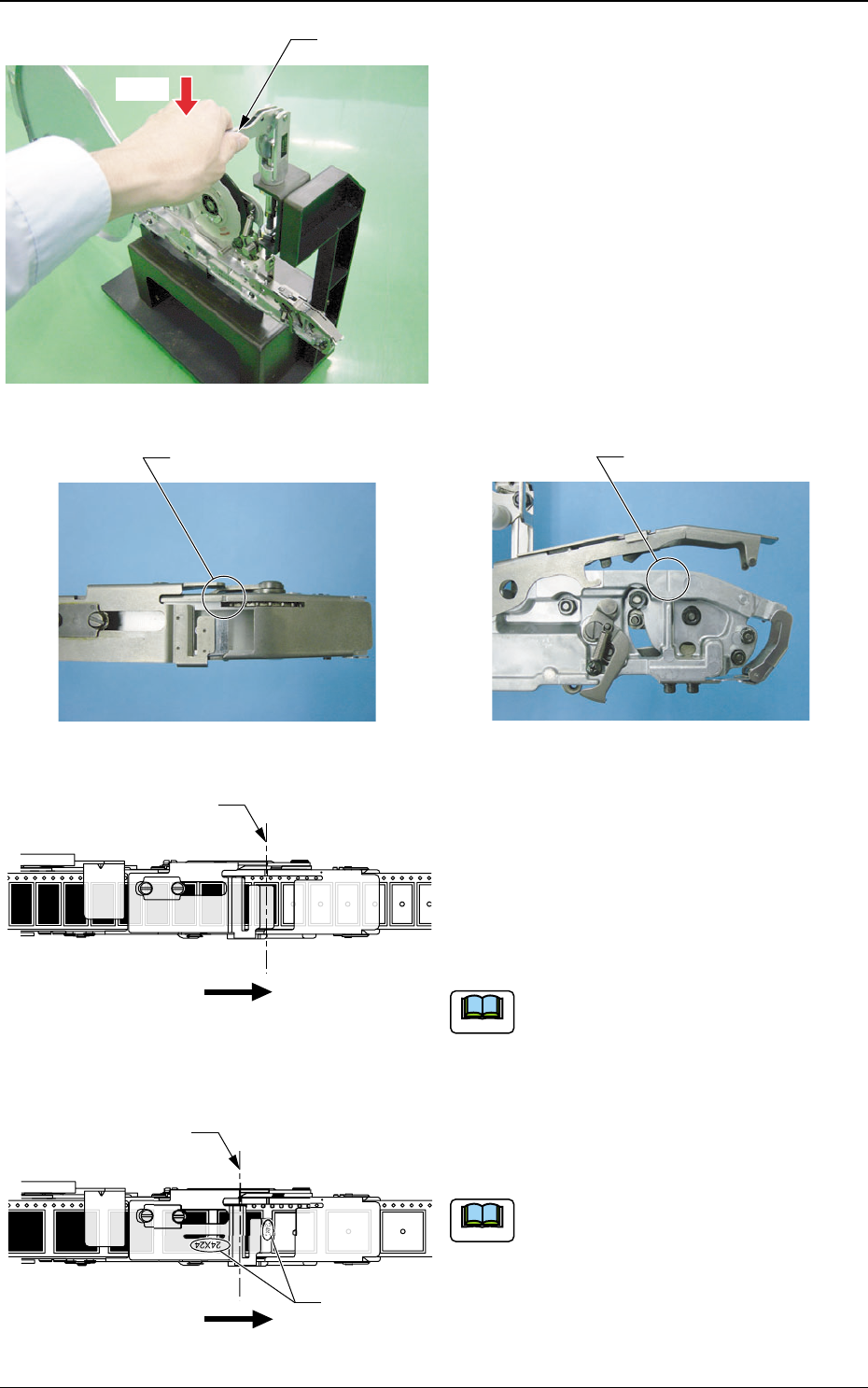
Press
Feed Lever
• For tape feeders of 12 mm or wider, push
the feed lever of the feeder set jig and align
the component center with the component
center set position.
The component center set position is marked on
the suppressor and the body section.
Marking
Marking
Fig. 34
Fig. 35 Marking (Suppressor)
Fig. 36 Marking (Body Section)
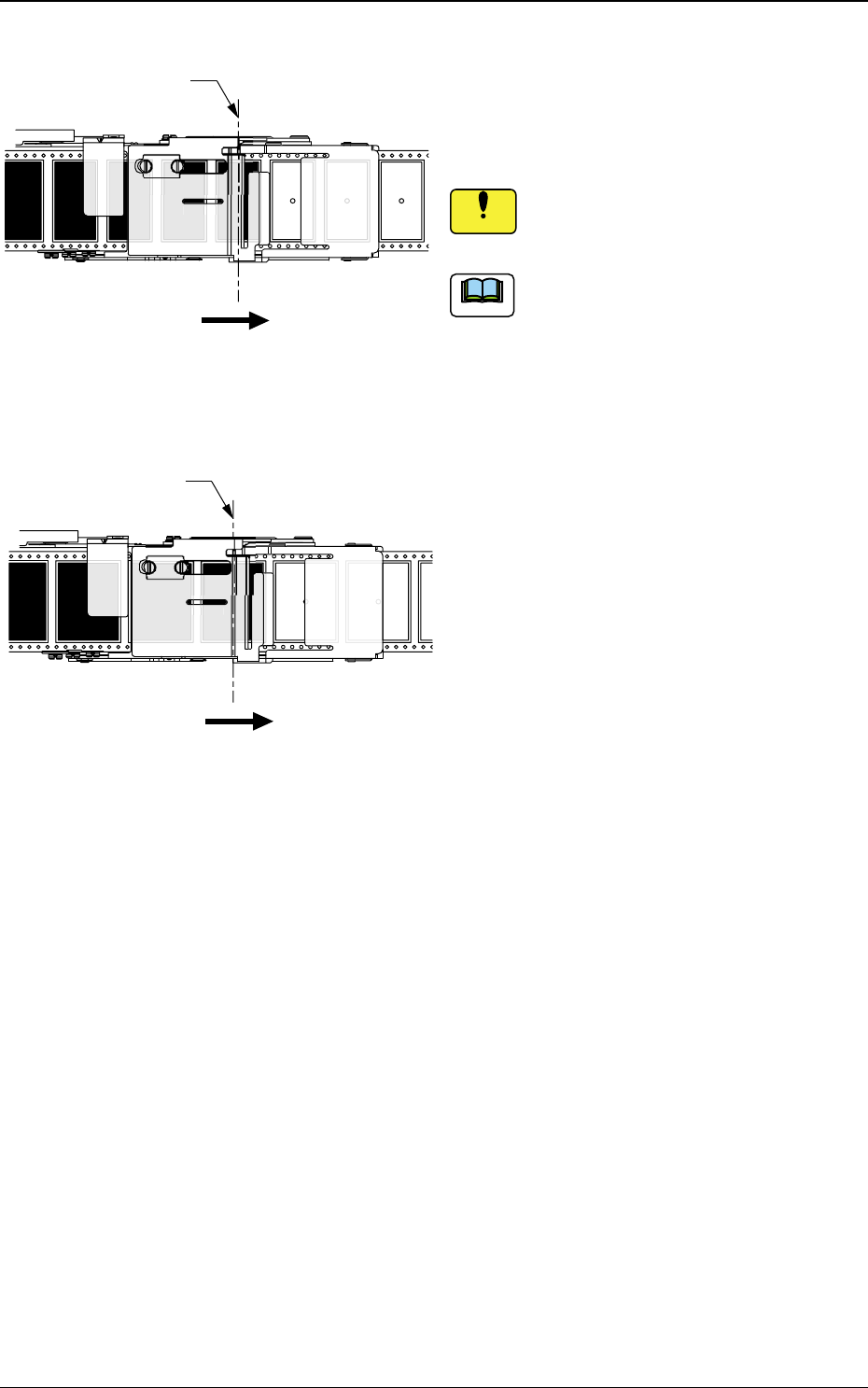
The Component Center Positions and
Component Center Set Positions for TF-
1210, TF-1211, TF-1212, TF-1610, TF-
2410, TF-3210 and TF-4410 (The figure
shows TF-2410).
The set position is the same as the pick-up
position.
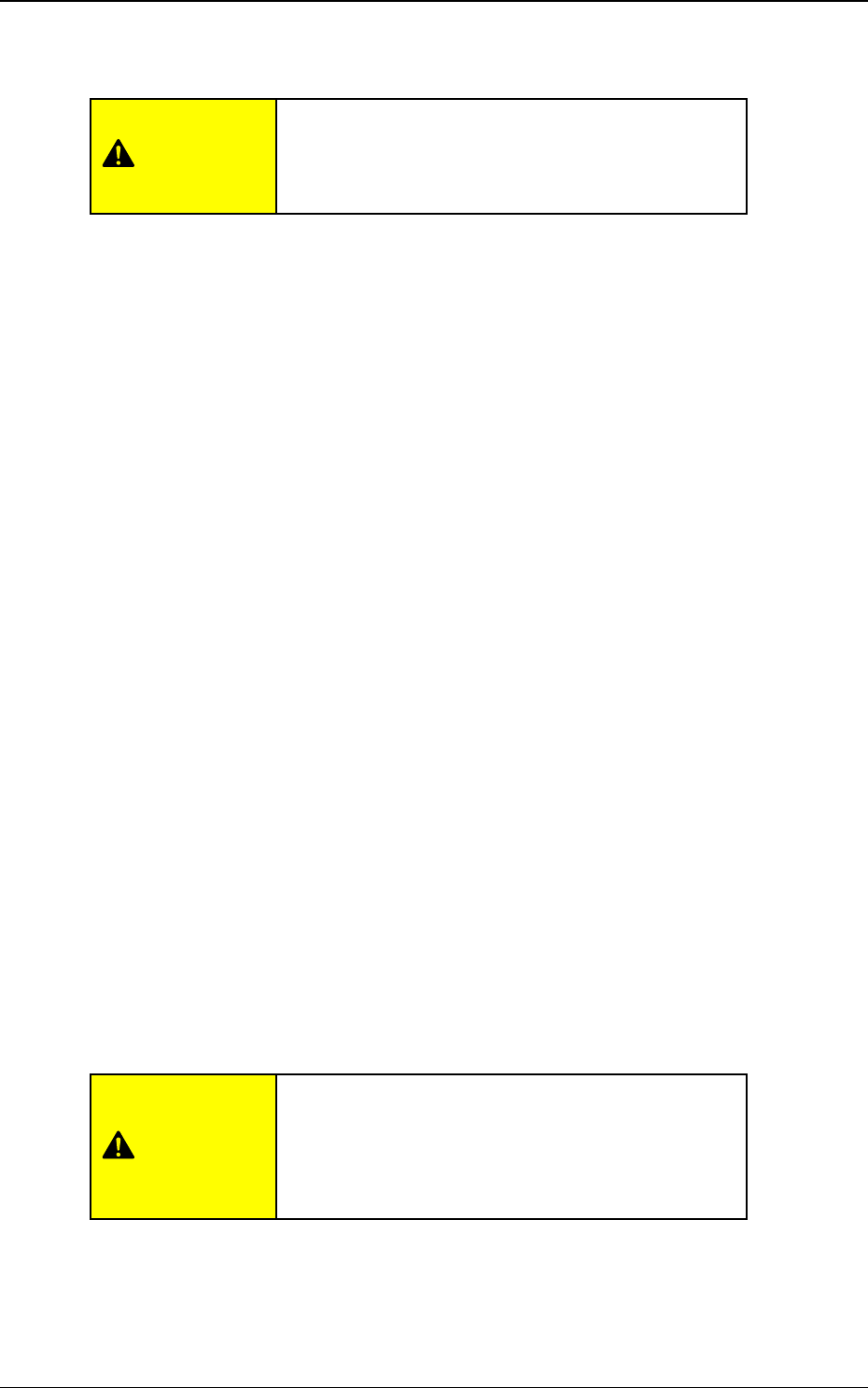
The Component Center and Component
Center Set Position for TF-2411 and TF-
3211(The figure shows TF-2411).
The component center is set at a position
different from that of the pick-up because
the feeder is for two or more feedings.
Forward Direction
Component Center Set
Position (Pick-up Position)
24
Forward Direction
Component Center Set Position
for the Feeders with Two or More
Feeding Operations
On tape feeders with two or
more feedings, the feed pitch
amount is marked.
Fig. 37
Fig. 38
Note
Note
Tg0409-PM-SO0410-002 23
2.3 Component Pick-up Position Alignment
Component Center and Component Center
Set Position for TF-4411 (In the case of tape
feeds of 24 mm pitch)
The set position varies with the pitch.
Two or more tape feedings are required, so
set the component center position slightly
away from the pick-up position.
Component Center and Component Center
Set Position for TF-4411 (In the case of tape
feeds of 32 mm pitch)
Notice
:
:
:
Forward Direction
Component Center Set Position for Tape
Feeds of 24 mm pitch
4/3
3
3
2
3
4
4
4X
2
2
44X24
/
3
2
Forward Direction
Component Center Set Position for Tape
Feeds of 32 mm pitch
Fig. 39
Fig. 40
Note
Tg0409-PM-SO0410-002 24
3. Tape Feeder Attachment
3. Tape Feeder Attachment
3.1 Items to be checked before attaching the tape feeder
on the feeder carriage
Before the tape feeder is attached on the feeder carriage of the chip mounter
(TCM-X series), check the following items:
• Make sure that the front hook is caught by the pin when the sup-
pressor is lowered.
• Make sure that the suppressor holding lever is caught by the
suppressor hook when the suppressor is lowered.
• Make sure that the cover tape is not caught in the suppressor.
• Make sure that there is no slack in the cover tape and that it is
properly taken up in the take-up reel socket through the roller
section.
• Turn the take-up reel socket in the proper direction and make sure
that the plate spring is inserted until locked.
• Make sure that there is a component on the pick-up position.
• Make sure that the tape excess is appropriate (10 mm or less).
When the tape feeder is attached on the feeder
carriage, always make sure that the feeder car-
riage has been returned to its home position.
CAUTION
When the tape feeder rises, the vacuum nozzle or
the machine might be damaged and leading to a
pick-up error.
Set the tape feeder correctly.
CAUTION