OM-1058-002.pdf - 第33页
Tg0409-PM-SO 0410-002 32 4.1 Feed Pitch Selecting Procedure (3) Remove the set screw for the tape take- up link with a driver and remove the tape take-up link from the pitch selecting section on the swing arm. (4) Attach…
Tg0409-PM-SO0410-002 31
4. How to Select the Feed Pitch
For TF-1610, TF-2420, TF-3210, TF-4410 and TF-4411, the feed pitch is
changed as required.
Refer to "1.1 Types of Tape Feeders" for feed pitch amount.
4.1 Feed Pitch Selecting Procedure
• The feed pitch selecting procedure is described, taking as examples from 4
mm to 12 mm in TF-1610.
The same procedure applies to other tape feeders except for those given
special descriptions.
4. How to Select the Feed Pitch
Reference
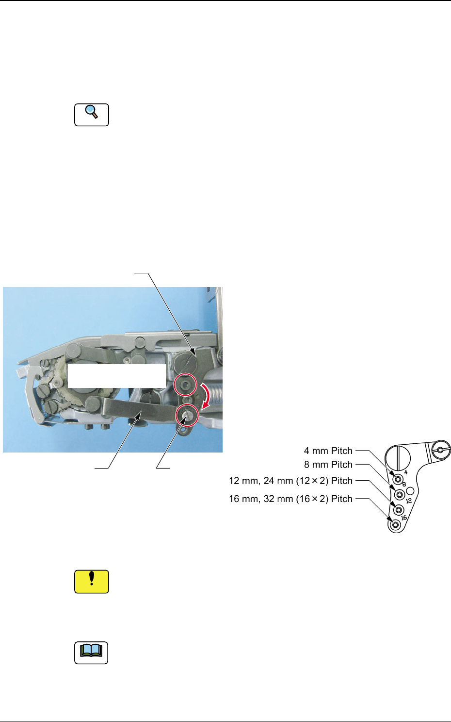
(1) Remove the set screw for the tape feed
link, using a driver, and remove the tape
feed link from the pitch selecting section
on the swing arm.
(2) Attach the tape feed link on the position
which is correct for the tape feed pitch.
Attach the set screw together with flat
and spring washers.
Fig. 51
Fig. 52 Pitch Selecting Section on the Swing Arm
The torque for the set screw fastening is 0.686 N.m (7 kgf.cm).
If the set screw is fastened with too much torque, the screw
section might be deformed.
The caution applies to the other screw removals and attachments.
(a) The attachment position to be changed is marked on the pitch
selecting section.
(b) Tape feeders such as TF-2411, TF-3211 and TF-4411 are for two
or more feedings, so attach the tape feed link at 12 mm for the 24
mm pitch or at 16 mm for the 32 mm pitch.
Notice
Note
Tape Feed Link Set Screw
Pitch Selecting Section
on the Swing Arm
Change the attachment
position.
Tg0409-PM-SO0410-002 32
4.1 Feed Pitch Selecting Procedure
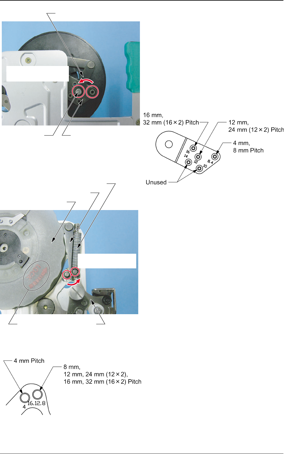
(3) Remove the set screw for the tape take-
up link with a driver and remove the
tape take-up link from the pitch selecting
section on the swing arm.
(4) Attach the tape take-up link on the
position which is correct for the feed
pitch. Attach the set screw together with
flat and spring washers.
(5) Turn the take-up reel socket in the
direction away from the arrow (Refer to
"Note" in Fig. 55), and remove it.
(6) Remove the take-up reel feed spring from
the spring hook on the swing arm side.
(7) Attach the feed pitch selecting sliding
section on the tape take-up link to a
position appropriate for the feed pitch.
(8) Catch the take-up reel feed spring on
the pin hook on the tape take-up link
attached on the changed position.
(9) Turn the take-up reel socket to the arrow
direction (Refer to "Note" in Fig. 55) and
attach it.
If the take-up reel socket is not set
correctly, the take-up reel socket might
come off during operation, which might
cause the machine to malfunction. Turn
the take-up reel socket in the direction
of the arrow (Refer to "Note" in Fig. 55)
and confirm that the plate spring is
inserted until it locks.
Fig. 53
Fig. 54 Pitch Selecting Section on the Swing Arm
Fig. 56
Fig. 55
Tape Take-up Link
Reel Drive Pitch
Selection Section
Set Screw
Change the attachment
position.
Tape Take-up Link
Change the attachment
position.
Note
Take-up Reel Socket
Swing Arm
Take-up Reel Feed Spring
Tg0409-PM-SO0410-002 33
4.1 Feed Pitch Selecting Procedure
(a) When the pitch is changed from 4 or 8
mm to 12 or 16 mm in TF-1610, it is
necessary to change the take-up spring
(Refer to Table 3).
(b) Attach and store the unused take-up
spring onto the housing spring hook in
order not to lose it (Refer to Fig. 57).
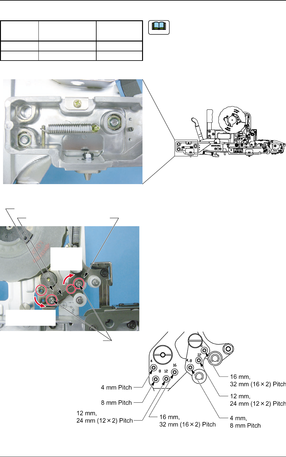
(10) Remove the set screw on the slack link
with a driver and remove the slack link
from the slack lever and the swing arm.
(11) Attach the slack link onto the position
which is correct for the pitch. Attach the
set screw together with the flat and
spring washers.
Tape Feeder of TF-1610
Slack Link
Change the
attachment
position.
Change the
attachment position.
Slack Lever
Set Screw
Swing Arm
Fig. 57 Take-up Spring Housing Condition
Fig. 58
Fig. 59 Slack Lever and Swing Arm
Table 3
Note
Identification
None
White Marking
4, 8
12, 16
Feed Pitch
(mm)
Max. Take-up Load
(gf)
2
3.6