OM-1058-002.pdf - 第59页
Tg0409-PM-SO 5.3.5 Quarterly Maintenance 0410-002 58 5.3 Maintenance Method Fig. 86 Fig. 85 T able 9 Pick-up Position (Fig. 86) Feeder Adjusting Jig Fig. 86 Check, Adjustment Pick-up Position Reference Drawing W ork W or…
Tg0409-PM-SO0410-002 57
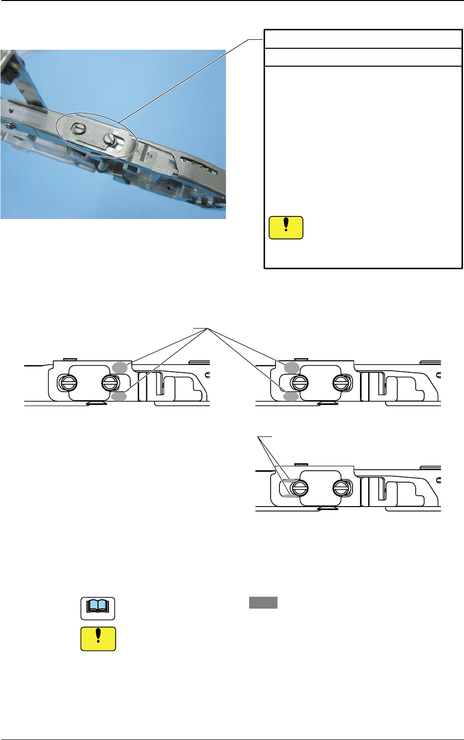
5.3 Maintenance Method
Fig. 84
Apply grease on the section of .
Too much grease might adhere to the rear side of the shutter, and
so might cause a pick-up error.
:
:
:
Shutter Closed
Shutter Opened
Apply it on the contact surface of the
shutter sliding guide and the shutter base.
Shutter Sliding Guide
Every month Lubrication
Lubricate it, using the following procedure.
1. Drip alcohol on the shutter sliding guide.
2. Air-blow it.
3. With a thin bar, apply Daphne Eponex
Grease No. 1 on the contact surface of
the shutter sliding guide and shutter base.
4. Open the shutter and apply Daphne
Eponex Grease No. 1 between the shutter
sliding guide and the suppressor, with a thin
bar.
5. Move the shutter backward and forward to
create a smooth coating of grease.
Inadequate maintenance of the
shutter section may allow foreign
substances enter, and rust might
cause malfunction.
Notice
Appl
y
it
b
etween the shutter slidin
g
g
uide
and the suppressor.
Notice
Note
Tg0409-PM-SO
5.3.5 Quarterly Maintenance
0410-002 58
5.3 Maintenance Method
Fig. 86
Fig. 85
Table 9
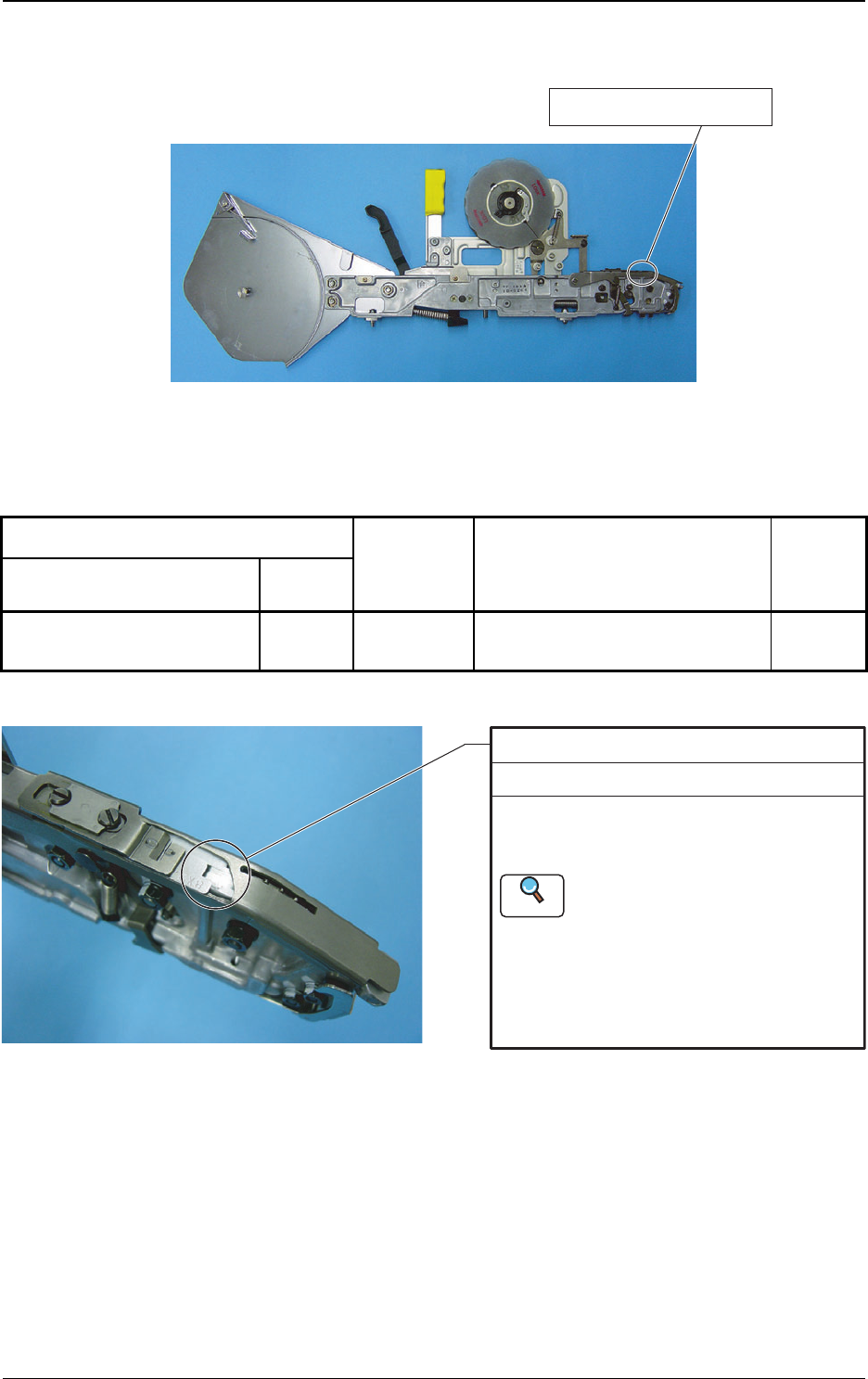
Pick-up Position (Fig. 86)
Feeder Adjusting JigFig. 86 Check,
Adjustment
Pick-up Position
Reference
Drawing
Work Working Tools
Name
Location to be maintained
Check
Pick-up Position
Check and Adjustment Every Three Months
Check the pick-up position, using the feeder
adjusting jig JG-0148.
If the pick-up position is not correct, adjust it.
For details of pick-up position
adjustment, see the Instruction
Manual for the Feeder Adjusting
Jig JG-0148.
The "Work Procedure (3) in 5.3.4
Pick-up Position Adjustment to
Direction Y" is not required.
Reference
Tg0409-PM-SO0410-002 59
6. Maintenance Component List
This describes the components where maintenance is required. Always
check the component of which the use cycle is passed.
If there are any worn or damaged components, replace them.
Use Limit : One Year (or 10,000,000 Operations)
(a) The components to be used vary, depending on the applicable tape
feeder.
(b) The figures in brackets in the following figures show Key No.
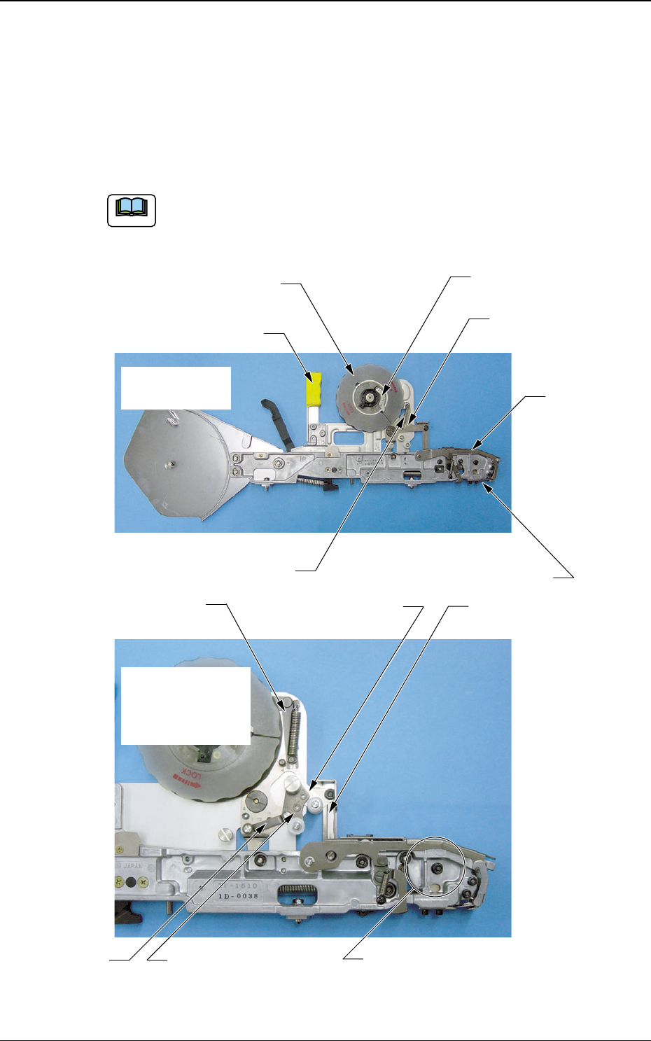
6. Maintenance Component List
Fig. 87
Note
Identification Tube
TUBE, WIRING (5-05, 5-06, 5-07)
Suppressor Assembly
ASSY, LEVER
(104, 105, 107)
Swing Arm Assembly
ASSY, LEVER (304)
Take-up Reel Feed Spring
SPRING, TENSION (313, 314, 332)
Reel Socket Assembly
ASSY, DISK (315, 316)
Plate Spring
SPRING, FLAT (316, 317)
Swing Arm Assembly
ASSY, LEVER (214)
Front Hook Assembly
ASSY, HOOK(FRONT HOOK) (101)
Feed Lever Assembly
LINK (303)
Slack Lever Assembly
ASSY, LEVER (336)
Slack Link
LINK (335)
Tape Take-up Link Assembly
ASSY, LEVER (312, 330)
Tape Feeder of
8 mm Width
Sprocket Assembly
ASSY, SPROCKET (237)
(Only for Tape Feeder of 32 or 44 mm Width)
Tape Feeders of
12 mm Width
or more
(Photo of TF-1610)