OM-1058-002.pdf - 第95页
Tg0409-PM-SO Fig. 105 Fig. 106 T able 27 Embossed Carrier T ype T aping (a) A 0 × B 0 stands for the rectangle hole size on the tape. The clearance between a rectangle hole and a component af fects the pick- up rate. Use…

Tg0409-PM-SO
Table 26
0410-002 93
8.6 Specifications of 32 mm Tape Feeder (For Embossed Tape)
8.6 Specifications of 32 mm Tape Feeder (For Embossed
Tape)
Tg0409-PM-SO
Fig. 105 Fig. 106
Table 27
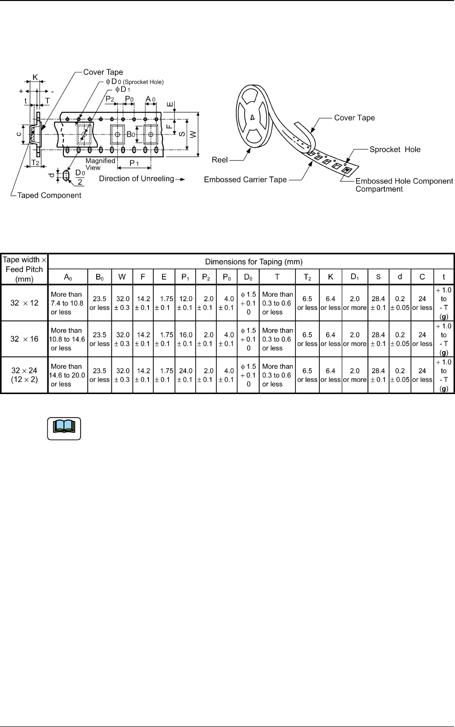
Embossed Carrier Type Taping
(a) A0 × B0 stands for the rectangle hole size on the tape.
The clearance between a rectangle hole and a component affects the pick-
up rate. Use the taping component with appropriate clearance specifica-
tions.
(b) The above specifications do not imply any guarantee of pick-up rate, etc.
The pick-up rate varies depending on how the main machine is adjusted
and the combination of the main machine and the tape feeders.
(c) Make a hole (D1) in the cavity if necessary.
(d) 10 pitches cumulative tolerance P0 should be ± 0.2 mm.
(e) The cover tape should run smoothly along the sprocket holes. The edges
of the cover tape should be aligned with the carrier tape (taping).
The thickness of the cover tape should be 0.07 mm or less (including
adhesion).
0410-002 94
8.6 Specifications of 32 mm Tape Feeder (For Embossed Tape)
8.6.1 Referential Dimension for Taping
Note
Tg0409-PM-SO
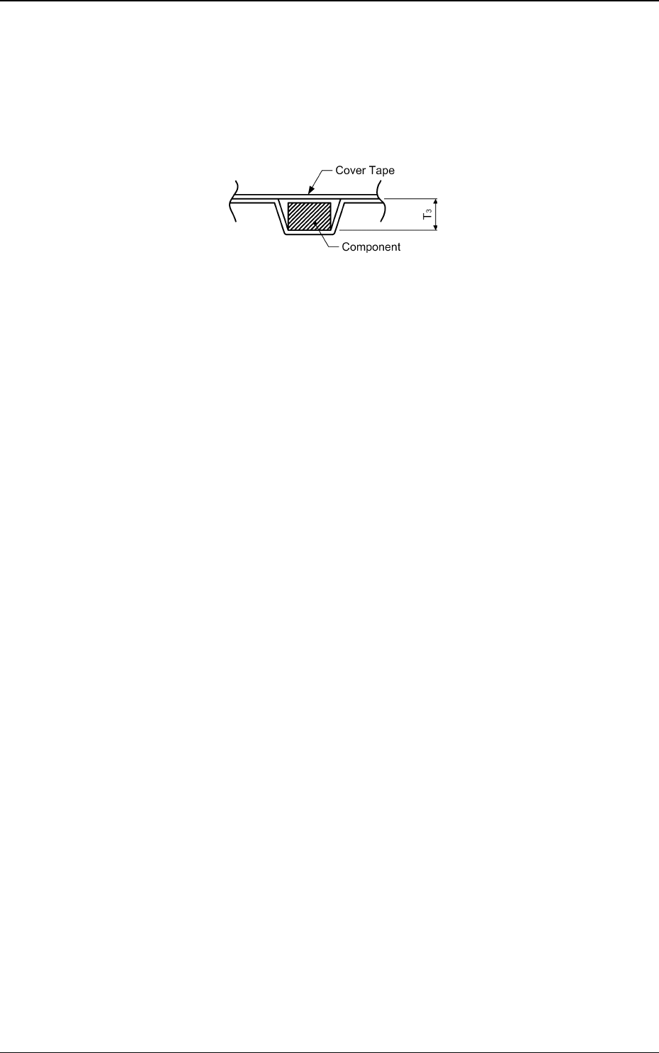
Fig. 107
(f) Use a taping on condition that the component itself or its electrical contact
is not protruded from the upper surface of tape.
Embossed Taping
"Embossed depth (T3) > Component thickness"
(g) Shown in column "t" is the gap between the component pick-up and chute
surfaces.
As the gap can be adjusted by the stroke control, set the pick-up level data
in the component library data.
If dimension "t" is big, components may not stay still or may be tilted. Be
sure to adjust the dimension for the appropriate one in the range of values
specified in the table.
(h) The shape of component pick-up surface should be wide and smooth
enough to be picked up by vacuum nozzles.
(i) Cover tapes sometimes become thicker than expected due to leafy and
fluffy leftovers produced through the production process. However, the
overall thickness should not exceed the value described as "T2" in the
table.
(j) In the case of feed pitch of 24 mm, the feeding is performed twice, each
time with 12 mm. Confirm the pick-up position when the tape is set.
(The pick-up position and the initial set position are different from those
for single feeding operations).
0410-002 95
8.6 Specifications of 32 mm Tape Feeder (For Embossed Tape)