YSM20&40_how_to_change_directionPDFA.pdf - 第2页
Service Engineer Service Information SI1407002E - 000 =YSM40_How to change the board flow direction (Tentative measure) 2/ 24 Table of contents 1. Create a work spa ce ....................................................…
Service Engineer
Service Information
SI1407002E-000=YSM40_How to change the board flow direction (Tentative measure)
1/24
MACHINE TYPE : YSM40-2, YSM40-4
SOFTWARE VERSION : Ver4.42STD R1.000
CLASSIFICATION : Installation / Adjustment / Machine setting / Specification
YSM40_How to change the board flow direction (Tentative measure)
General description
This document describes how to change the board flow direction of the YSM40 machines.
The procedure described in the document is tentative, and the document that describes the
permanent measures will be provided later. Use this document when in urgent need.
About this document:
This document is intended for Service engineers.
YAMAHA is not responsible for any problems caused by the misuse of the document.
This document contains the method to edit the system data that affects the customer’s machine
condition.
Make sure to thoroughly understand the contents of the document, and perform the adjustments
on your own responsibility.
About the safety:
Strictly follow the safety precautions in the “Safety” section in the “Operation Manual”.
Disclaimers:
This document contains the preliminary information subject to change in the future.
The information contained in this document represents the current view of YAMAHA on the issues
discussed as of the date of issuance. As YAMAHA must respond to changing market conditions, it
should not be interpreted to be a commitment on the part of YAMAHA, and YAMAHA cannot
guarantee the accuracy of any information presented after the date of issuance.
This document is provided for information purposes only, and it is provided without any warranties,
either express or implied.
It is the responsibility of the user to comply with all applicable copyright laws. Without limiting the
rights under copyright, no part of this document may be reproduced, stored in or introduced into a
retrieval system, or transmitted in any form or by any means (electronic, mechanical, photocopying,
recording, or otherwise), or for any purpose, without the written permission of YAMAHA.
However, this shall not be construed to limit the user’s right granted by Copyright law.
YAMAHA may have patents, patent applications, trademarks, copyrights, or other intellectual
property rights covering subject matter in this document. Except as expressly provided in any
written license agreement from YAMAHA, this document does not give users any license to these
patents, trademarks, copyrights, or other intellectual property.
The names of actual companies and products mentioned in this document may contain the
trademarks of their respective owners.
No: SI1407002E-000
ISSUED DATE: December 4, 2014

Service Engineer
Service Information
SI1407002E-000=YSM40_How to change the board flow direction (Tentative measure)
2/24
Table of contents
1. Create a work space ......................................................................................................................... 3
1.1 Remove the tape cutter duct .................................................................................................... 3
1.2 Remove the slope .................................................................................................................... 5
1.3 Remove the ANC unit ............................................................................................................... 6
2. Change the board flow direction ..................................................................................................... 7
2.1 Change the positions of the Transit position sensors .............................................................. 7
2.2 Change the wiring .................................................................................................................. 11
2.2.1 Change the location of the Entrance and Exit sensors and connector pins (Tentative measure) . 11
2.2.2 Interchange the signal wires (NEXT, PREVIOUS) ........................................................................ 12
2.3 Adjust the optical axis of the sensor ....................................................................................... 13
2.4 Adjustment of the sensor amplifier (KLF-M654N-10) ............................................................. 14
3. Things to do after changing the board flow direction ................................................................ 17
3.1 Change the machine setting................................................................................................... 17
3.2 Adjustments to be performed by the CalibSm........................................................................ 17
3.2.1 “Adj. Conveyor Guide Check Pos.” ............................................................................................... 18
3.2.2 “Adj. Data Check Origin” ............................................................................................................... 20
3.2.3 “Transfer Distance” adjustment .................................................................................................... 23
3.2.4 “ANC Swap”.................................................................................................................................. 24
Service Engineer
Service Information
SI1407002E-000=YSM40_How to change the board flow direction (Tentative measure)
3/24
1. Create a work space
When changing the board flow direction of YSM40, some parts of the machine need to be
removed to create a work space.
This section describes how to remove the parts.
1.1 Remove the tape cutter duct
For the YSM40, 4-Beam type machine, remove the tape cutter duct and the slope to create a work
space.
For the YSM40, 2-Beam type machine with the c-ATS, remove the cutter unit to create a work
space.
Note:
If the tape cutter is detachable and the customer has the tape cutter carrier, remove the tape cutter for
the better workability.
If the customer does not have the tape cutter carrier, remove the slope. (It is the same as the procedure
for the 4-Beam type machine.)
1. Turn OFF the power supply and the air supply.
Caution:
You will need to work under the base. In order to prevent the transformer and the electric part from
shorting out by touching them with a tool (drivers, wrenches and so on), make sure to turn OFF the
power at the main breaker.
Warning:
As the protection cover of the tape cutter is removed during the work, make sure to shut OFF the air
supply at the main valve.
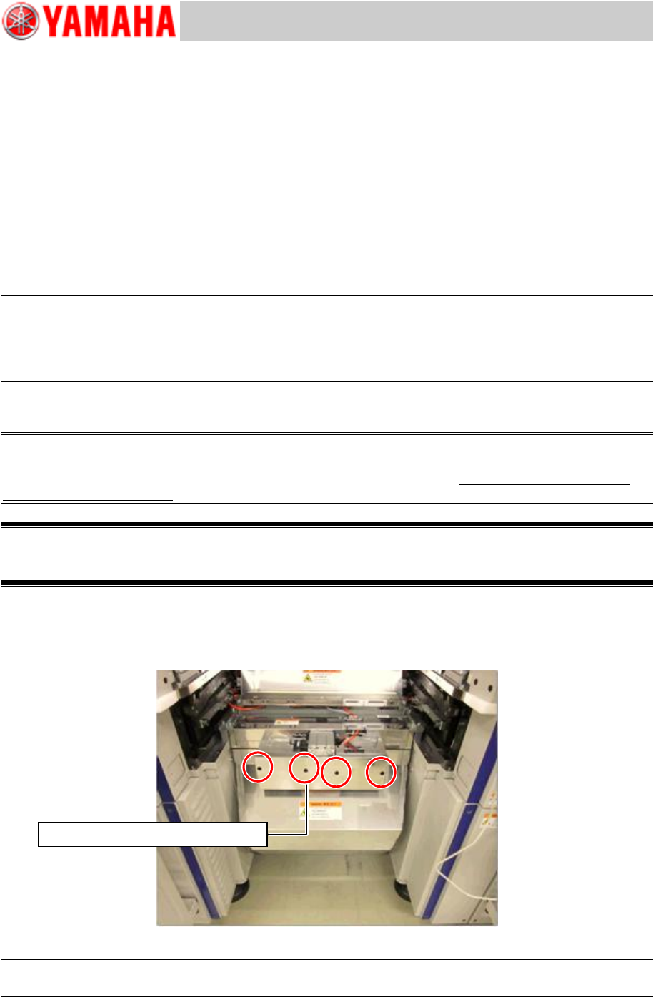
2. Loosen the screws of the tape cutter duct.
Insert a driver into the screw holes (Qty: 4) on the front cover and loosen the screws.
As the screw holes of the cover are U-shaped, you do not need to remove the screws.
Figure 1
Note:
For removing the screws, use a driver 100mm or longer
Use a screwdriver 100mm or longer