YSM20&40_how_to_change_directionPDFA.pdf - 第10页
Service Engineer Service Information SI1407002E - 000 =YSM40_How to change the board flow direction (Tentative measure) 10 / 24 5. Adjust the position of the sensor (Emitter) and route the fiber w ire. Attach the em itte…
Service Engineer
Service Information
SI1407002E-000=YSM40_How to change the board flow direction (Tentative measure)
9/24
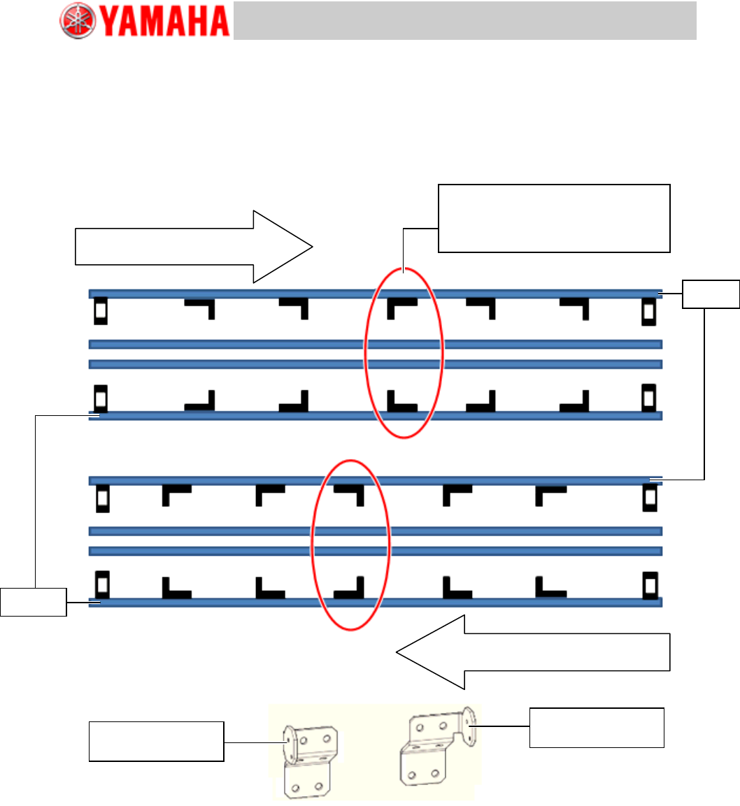
4. Temporarily attach the brackets.
Attach the brackets removed in step 2. Interchange the brackets between the Lane 1 and the Lane
2.
See the figure below for the orientation of the brackets.
As the optical axis position of the sensor will be adjusted later on, attach the brackets only
temporarily.
[Orientation of the brackets]
Figure 10
Board flow direction:
From Left to Right
Board flow direction:
From Right to Left
Set the other type of the bracket of
the brackets on the same lane.
KLF-M912A-01
BRKT., SENSOR
Lane 1
Lane 2
KLF-M912A-51
BRKT., SENSOR
Service Engineer
Service Information
SI1407002E-000=YSM40_How to change the board flow direction (Tentative measure)
10/24
5. Adjust the position of the sensor (Emitter) and route the fiber wire.
Attach the emitter side fiber sensor to the temporarily attached bracket, and adjust the position to
the receiver side sensor that was positioned in step 3.
[Things to bear in mind when routing the fiber sensor]
Avoid the chip dump box position when routing the fiber wire.
Note:
As the chip dump box is removed during the work, if you route the wire to the box position, you will not
be able to set the box later on.
Make sure that the fiber wire does not interfere with the moving parts of the machine (Board
clamp, sideview lighting of the multi camera, blow station, PU-axis and so on).
Fiber wire is basically routed to outside the conveyor. However route it inside the conveyor at
the blow station area as the blow station moves up and down.
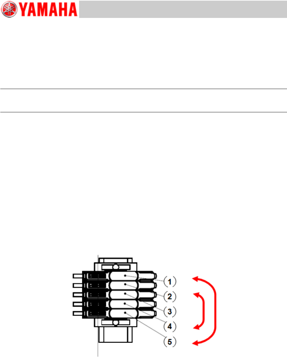
6. Change the positions of the fiber wires at the amplifier.
When changing the board flow direction by the procedure described in this document, the fiber
sensor position is changed. Therefore, the positions of the fiber wires at the amplifier need to be
changed.
Interchange the positions of the following fiber wires.
(1) and (5)
(2) and (4)
(3) does not need to be changed.
Figure 11
Service Engineer
Service Information
SI1407002E-000=YSM40_How to change the board flow direction (Tentative measure)
11/24
2.2 Change the wiring
2.2.1 Change the location of the Entrance and Exit sensors and connector pins
(Tentative measure)
As interchanging the harnesses of the Exit/Entrance sensor requires a lot of man-hours, change
the pin configuration of the connector (CN22) connected to the I/O conveyor board.
Note:
The procedure described in this section (changing the position of the connector pins) is used
temporarily.
A relay harness is planned to be added as a permanent measure. (Under review)
The work described in this document is NOT normally performed. When you need to change the board
flow direction, please make sure to contact YAMAHA.
Figure 12
1. Remove the slope on the rear side of the tape cutter unit.
If the slope is not removed, remove it referring to “1.2 Remove the slope”.
2. Remove the base cover.
Remove the base cover on the back side, on the left side of YSM40.
The I/O board is behind the cover.
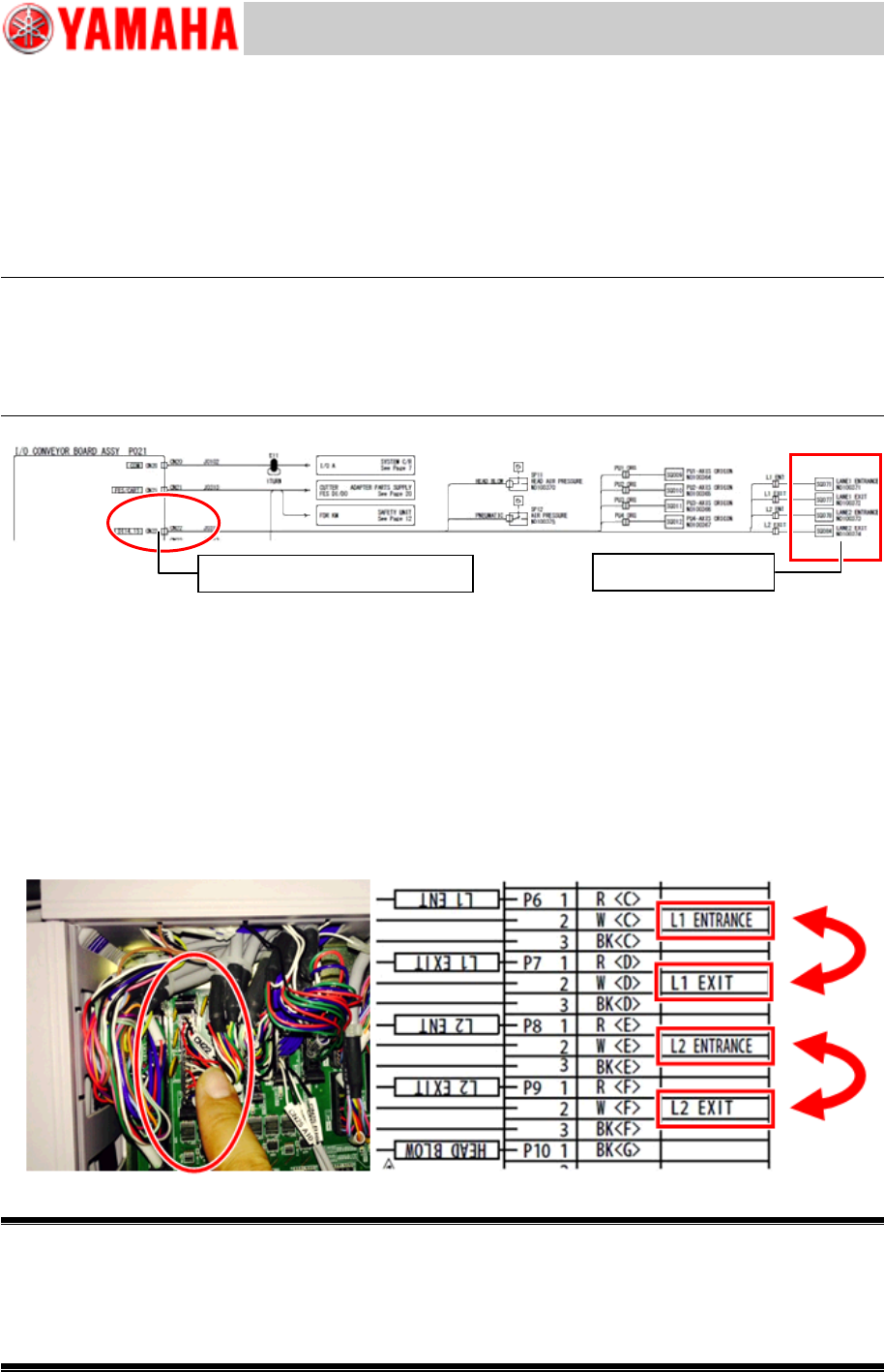
3. Remove the CN22 connector and change the pin configuration.
The connector second from the upper left of the I/O board is CN22.
Check the mark tube and disconnect the connector and change the location of the ENTRANCE
and the EXIT pins referring to the figure below.
Figure 13
Warning:
The procedure mentioned above is only a tentative measure.
Make sure to attach a label on the altered sensor so that other people can easily tell that the pin
configuration of the connector has been changed when they perform maintenance.
Also, make sure to release a report to YAMAHA to inform that you have changed the board flow
direction.
Conveyor sensor
Change the pin configuration