YSM20&40_how_to_change_directionPDFA.pdf - 第13页
Service Engineer Service Information SI1407002E - 000 =YSM40_How to change the board flow direction (Tentative measure) 13/ 24 2.3 A djust the optical axis of the sensor 1. Power ON the machin e. Power ON the m achine in…
Service Engineer
Service Information
SI1407002E-000=YSM40_How to change the board flow direction (Tentative measure)
12/24
2.2.2 Interchange the signal wires (NEXT, PREVIOUS)
In accordance with the change of the board flow direction, the connecting location of the signal
wire (NEXT, PREVIOUS) is supposed to be changed.
However, it requires a lot of man-hours for routing the wires and exchanging the connectors.
Although the wires cross each other, it does not affect the production. Route the signal wires
(NEXT, PREVIOUS) under the base.
Make sure to prepare 5m or longer signal wires (NEXT, PREVIOUS).
Item
Part Name
Part No.
Qty
Signal wire (5,000mm)
HNS,A.GATE2 L=5000
KV7-M66V1-02
2
Signal wire (10,000mm)
HNS,A.GATE2 L=10000
KV7-M66V1-12
2
Table 2
Discuss with the customer about the work previously, and if the signal wires need to be routed, you
need to route the wires, change the connectors and detach/attach the covers.
Note:
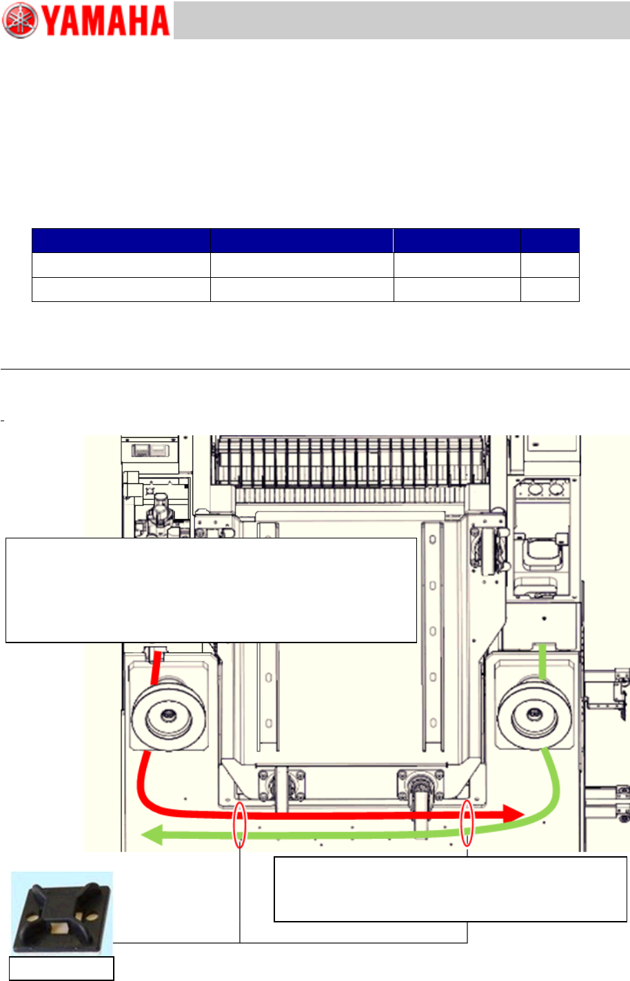
Make sure to route the wires so that they do not interfere with the Feeder exchange carriage/C-ATS
when removing/setting the unit.
Figure 14
Route the signal wire via the adjusting bolts (outer side) so that it
does not interfere with the Feeder exchange carriage/ C-ATS
when removing /setting the unit.
It is recommended to secure the wires at two (2) positions with
cable ties so that they do not sag.
Make sure to set the mount base 10mm inward from the
H-shaped pitted area on the base of YSM40 (Viewed
from underneath) to avoid the interference.
Mount base
Service Engineer
Service Information
SI1407002E-000=YSM40_How to change the board flow direction (Tentative measure)
13/24
2.3 Adjust the optical axis of the sensor
1. Power ON the machine.
Power ON the machine in order to adjust the positions of the sensor and the optical axis.
Warning:
DO NOT START SUPPLYING AIR until the tape cutter slope is set to the unit.
If the tape cutter accidentally starts, it is very dangerous.
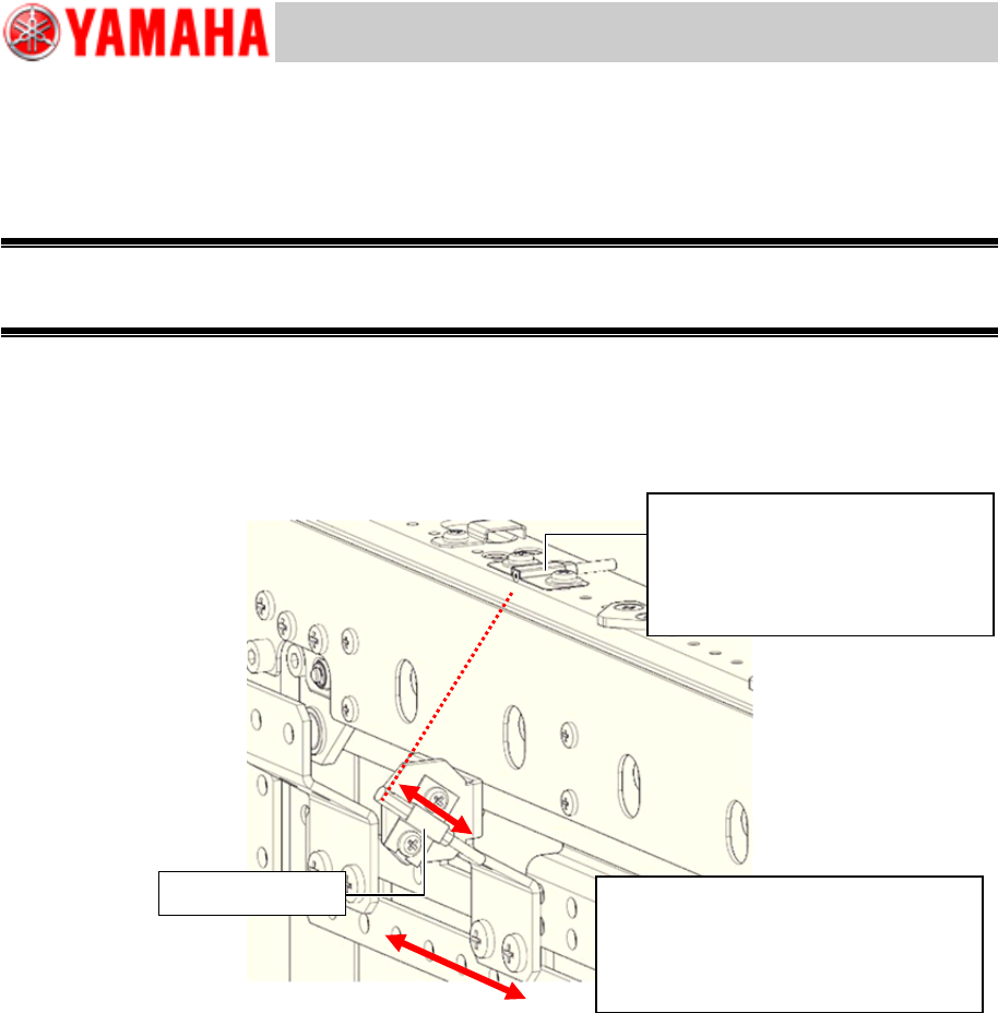
2. Adjust the optical axis of the sensor.
Adjust the emitter side optical axis position so that it is located in the center of the receiver side
sensor (whose position has been adjusted) by shifting the emitter side sensor.
Position the optical axis so that it is located in the center of the receiver head while checking the
value of the amplifier.
Figure 15
3. Check the address of the sensor position.
Make sure that the I/O address of the sensor is the same as the address of the fiber interchanged
in “2.1 Change the positions of the Transit position sensor, step 5”.
The Transit position sensor of YSM40 is usually in the OFF-state.
1) Click the [Sensor Light] button on the [Unit]-[Conveyor] window to make the sensor react.
2) Select “Conveyor” from the pull-down menu of “Input” on the [Unit]-[I/O] window.
3) Put your hand above the sensor to check if the sensor reacts at the address from N230000
through N230100. If it is detected, “DETECT 1” is displayed, if it is not detected, “NOT
DETECT 0” is displayed.
If the sensor reacts at the different position on the I/O window, the fiber position at the
amplifier is not appropriate.
Change the fiber position referring to “2.1 Change the positions of the Transit position
sensor”, step 6.
If the amplifier reacts but the I/O does not, the optical axis position may not be
appropriate.
Check the position by shifting the emitter side sensor from side to side. If the I/O still does
not react, move the sensor up and down.
Sensor (Receiver)
Make sure that the protrusion of
the sensor form the conveyor
edge should be 3mm or less.
Adjust the optical axis position so that
it is located in the center of the
receiver head while checking the
value of the amplifier.
Sensor (Emitter)
Service Engineer
Service Information
SI1407002E-000=YSM40_How to change the board flow direction (Tentative measure)
14/24
2.4 Adjustment of the sensor amplifier (KLF-M654N-10)
Perform only Power tuning. You do not need to adjust the amplifier.
When you accidentally initialize the setting or replace the amplifier, perform the adjustment for the
amplifier.
The currently shipped amplifier is initialized. If the initial setting is done for the amplifier, a label is
attached to it.
Item
Part Name
Part No.
Qty
Sensor amplifier
AMP, SENSOR 1
KLF-M654N-10
-
Table 3
* When replacing the amplifier due to defects, place an order for the required number of amplifiers.
[OUT selection indication: Orange]
* E3NDK-FA21, E3NX-FA7TW
* E3NDK-FA51, E3NX-FA9TW
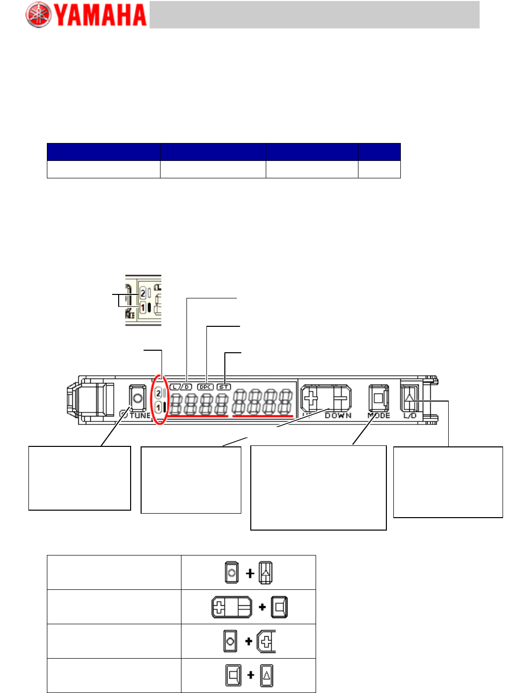
Figure 16
Setting Reset
Key Lock
Zero Reset
Solution Viewer
Table 4
[OUT Indication
light: Orange]
[L/D Indicator: Orange]
It indicates “Light ON/Dark ON” setting
[DCP Indicator: Green]
It turns ON when the “Dynamic Power Control” function is activated.
[ST Indicator: Blue]
It turns ON when the “Smart Tuning” is performed.
[OUT Indication light: Orange]
It turns ON when OUTPUT is ON
Switch OUTPUT
[L/D] button
By pressing the button once,
“Light ON” and “Dark ON”
are switched.
[L/D] indicator changes.
Threshold level
Switch “MODE/OUT”
[MODE] button
By holding down the button for 3
seconds or more, the “SET” mode
and the “RUN” mode are switched.
When holding down the button for 1
second, it is switched to “OUTPUT”.
Incident light
Fine tuning of the
Threshold level
[UP/DOWN] button
The green digital value
(Threshold) changes.
Sensitivity setting
[S.TUNE] button
Tuning is performed and
the [ST. Indicator] lights
up.