YSM20&40_how_to_change_directionPDFA.pdf - 第17页
Service Engineer Service Information SI1407002E - 000 =YSM40_How to change the board flow direction (Tentative measure) 17 / 24 3. Things to do after changing the bo ard flo w di rection 3.1 Change the machine setting Ch…
Service Engineer
Service Information
SI1407002E-000=YSM40_How to change the board flow direction (Tentative measure)
16/24
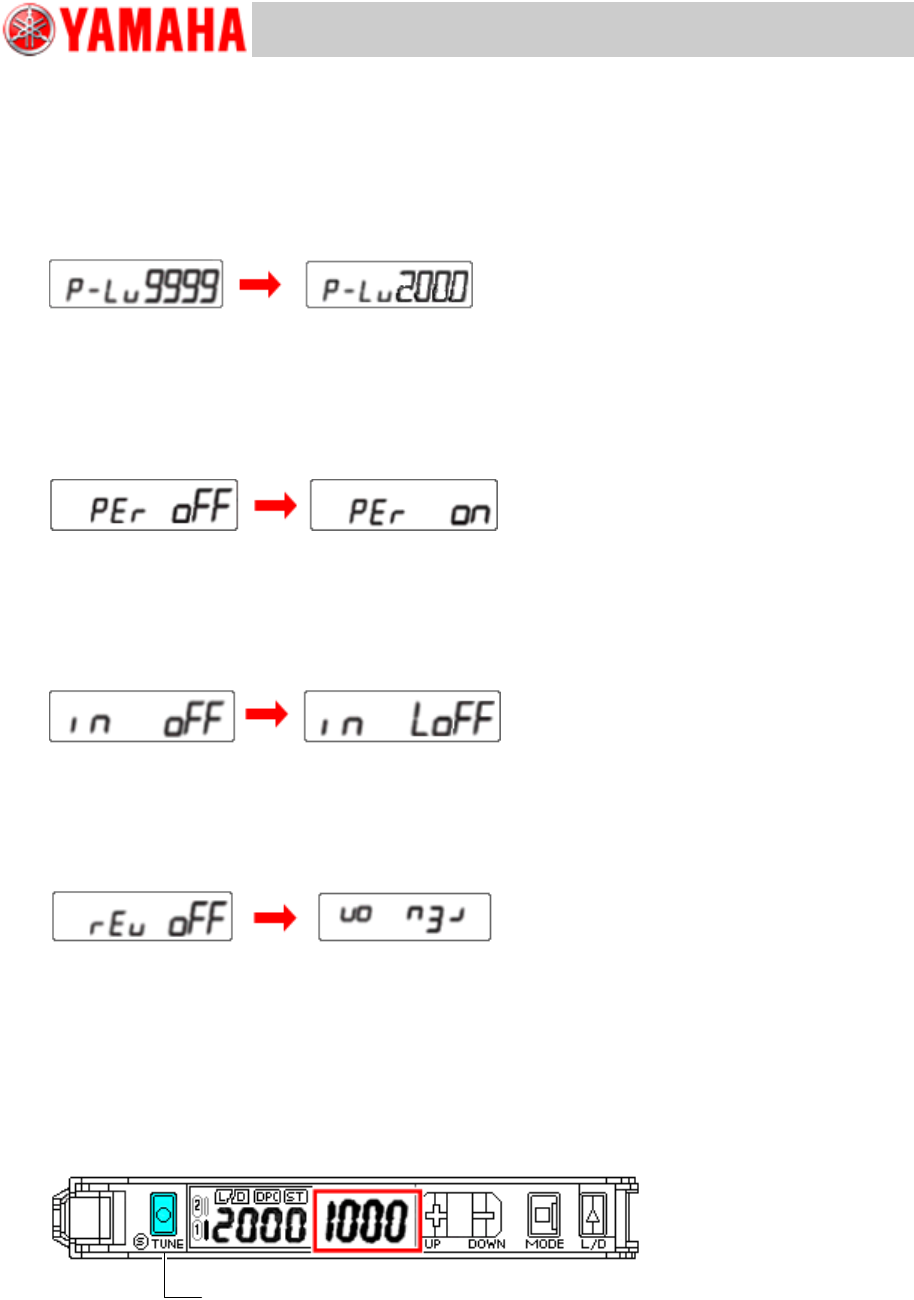
5. Set the Power tuning level to “2000”.
Set the target incident light level (Power tuning level) to “2000”.
You can set the power tuning level by pressing the [UP/DOWN] key. (Default: 9999. It is possible
to set from 1 through 9999.)
There are other items such as “BANK switching” and “Power Tuning ON/OFF Setting”. As the
settings for these items are not required, press the [MODE] key and skip it.
Figure 21
6. Set the Percentage Tuning to “ON” and the Tuning level to “-50%”.
Perform the setting to detect transparent objects and microscopic objects.
You can set the Percentage Tuning level by pressing the [UP/DOWN] key. (Default: -6%. It is
possible to set from -99% through 99%.)
Figure 22
7. Set the “External Input” to “LoFF”.
Change the type of the external light.
Select “LoFF” by pressing the [UP/DOWN] key and then press the [MODE] key to set.
Figure 23
8. Set “Inverted Display” to “ON”.
The digital display may be inverted depending on the mounting position of the amplifier. In this
case, set the “Inverted Display” to ON.
Figure 24
9. Switch the mode from “SET” to “RUN”.
After completing the procedures from step 3 through step 8, hold down the [MODE] key for three
(3) seconds or more to change the mode from “SET” to “RUN”.
10. Perform the Percentage Tuning.
Make sure that there is no board to be detected by the target sensor, and hold down the [S.TUNE]
key for one (1) second or more.
Figure 25
Tuning OFF
Tuning ON
Tuning OFF
Tuning ON
Hold down the [S.TUNE] key for 1 second or more. Make sure that the
incident light level is “2000” and the Threshold level is “1000”.
(The values may slightly vary depending on the adjustment state.)
Service Engineer
Service Information
SI1407002E-000=YSM40_How to change the board flow direction (Tentative measure)
17/24
3. Things to do after changing the board flow direction
3.1 Change the machine setting
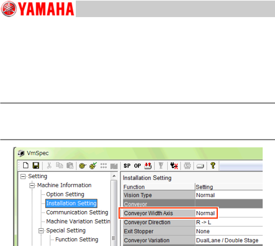
Change the setting of the board flow direction.
Click the [Machine] button and select “Setting” “Machine Information” “Installation Setting”
from the tree view on the left side of the VmSpec window and change the setting of “Conveyor
Direction”.
No password is required for changing the setting.
Caution:
Make sure to restart the machine after changing the setting of the board flow direction for the changes
to take effect.
The setting cannot be changed by just reading the board data, as the parameter is related to the drive
section.
Figure 26
3.2 Adjustments to be performed by the CalibSm
After changing the board flow direction and adjust the positions of the sensors, the following
adjustments need to be performed by the CalibSm.
[112 Check Conveyor]
[113 Transfer Distance]
[024 ANC Auto]
Service Engineer
Service Information
SI1407002E-000=YSM40_How to change the board flow direction (Tentative measure)
18/24
3.2.1 “Adj. Conveyor Guide Check Pos.”
The conveyor plate of YSM40 is movable so that the board clamped on the lane can be removed
by hand.
There are marks on the conveyor in order to judge whether the plate is back to the mounting lane
position or not. The mark position is the conveyor guide check position, and “Teaching” needs to be
performed for it.
* There are four (4) mark positions on each lane, so there are eight (8) positions all together.
Note:
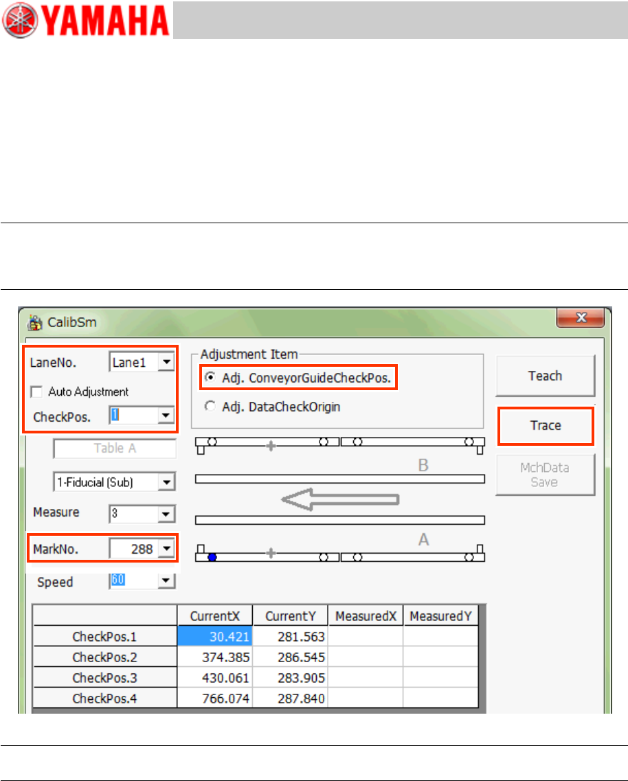
If you tick the “Auto Adjustment” checkbox, you can perform the “Adj. Conveyor Guide Check Pos.” and
the “Adj. Data Check Origin” adjustments at the same time.
Normally, tick the checkbox and perform the adjustments.
Figure 27
Note:
Use the Database No.288 to recognize the mark on the jig and check the position shift.
1. Tap the [112 Check Conveyor] button on the CalibSm main menu.
2. Make sure that the conveyor guide is at the mounting lane position.
3. Select “Adj. Conveyor Guide Check Pos.” from “Adjustment Item”.
4. Select the lane number (“Lane No.”) and the check position (“Check Pos.”) to be used for
the adjustment.
* The Table and the camera are automatically determined, so you do not need to set them.