YSM20&40_how_to_change_directionPDFA.pdf - 第20页
Service Engineer Service Information SI1407002E - 000 =YSM40_How to change the board flow direction (Tentative measure) 20 / 24 3.2.2 “Adj. Data Check Origin” YSM40 does not ha ve stoppers on the conv eyor. A lso the rel…
Service Engineer
Service Information
SI1407002E-000=YSM40_How to change the board flow direction (Tentative measure)
19/24
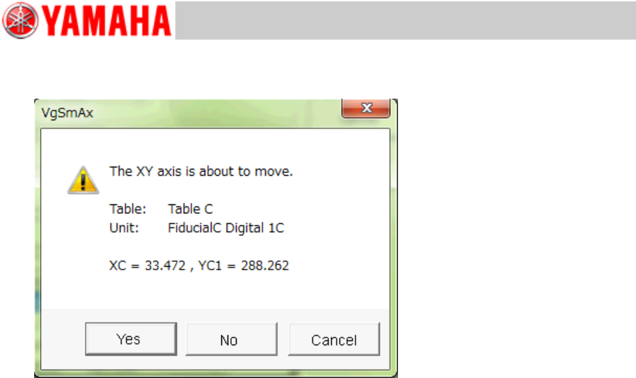
5. Tap the [Trace] button to move the camera to the measurement position.
Figure 28
If the mark is within the measurement range, tap the [Yes] button and move the camera to the
mark position and correct the position.
If the mark is out of the detection range, tap the [Teach] button and manually move the camera to
the mark position and perform teaching.
6. Change “Check Pos.” and “Lane Pos.” and adjust the check mark position of each
conveyor guide.
Service Engineer
Service Information
SI1407002E-000=YSM40_How to change the board flow direction (Tentative measure)
20/24
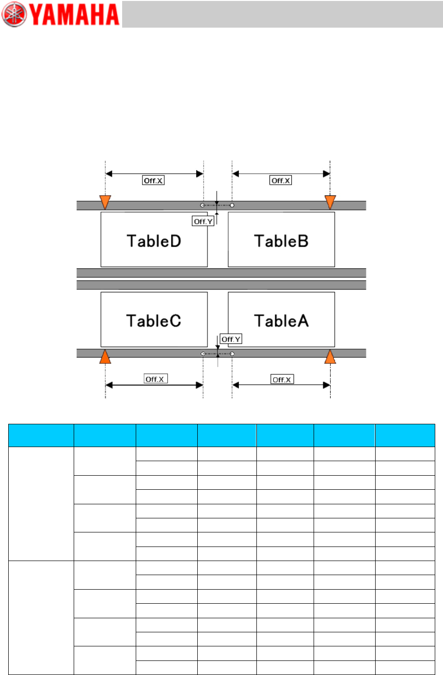
3.2.2 “Adj. Data Check Origin”
YSM40 does not have stoppers on the conveyor. Also the relation between the Edge Clamp
position and the Board clamp position is different from the relation of the existing machines.
The Edge clamp position and the Board clamp position are adjusted by using the conveyor guide
check position mark. Adjust the datum position for each table and lane.
[Relation between the data check datum position and the mark position on the conveyor]
<<YSM40-4>>
Figure 29
Board flow
direction
Table
Datum No.
Offset :X
Offset: Y
Edge
Clamp X
Edge
Clamp Y
Right Left
A
1
182.5
13.5
5
5
2
182.5
-13.5
5
-5
B
1
182.5
13.5
5
5
2
182.5
-13.5
5
-5
C
1
-182.5
13.5
5
5
2
-182.5
-13.5
5
-5
D
1
-182.5
13.5
5
5
2
-182.5
-13.5
5
-5
Left Right
A
1
182.5
13.5
-5
5
2
182.5
-13.5
-5
-5
B
1
182.5
13.5
-5
5
2
182.5
-13.5
-5
-5
C
1
-182.5
13.5
-5
5
2
-182.5
-13.5
-5
-5
D
1
-182.5
13.5
-5
5
2
-182.5
-13.5
-5
-5
Table 5
Service Engineer
Service Information
SI1407002E-000=YSM40_How to change the board flow direction (Tentative measure)
21/24
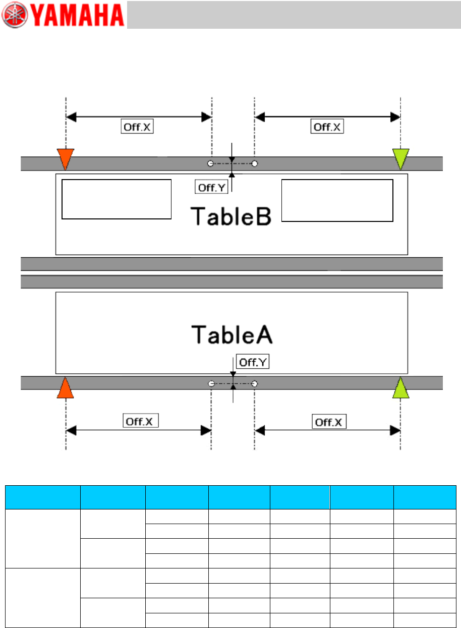
[Relation between the data check datum position and the mark position on the conveyor]
<<YSM40-2>>
Figure 30
Board flow
direction
Table
Datum No.
Offset :X
Offset: Y
Edge
Clamp X
Edge
Clamp Y
Right Left
A
1
-182.5
13.5
5
5
2
-182.5
-13.5
5
-5
B
1
-182.5
13.5
5
5
2
-182.5
-13.5
5
-5
Left Right
A
1
182.5
13.5
-5
5
2
182.5
-13.5
-5
-5
B
1
182.5
13.5
-5
5
2
182.5
-13.5
-5
-5
Table 6
Board flow direction:
Right Left
Data check origin
Board flow direction:
Left Right
Data check origin