YSM20&40_how_to_change_directionPDFA.pdf - 第21页
Service Engineer Service Information SI1407002E - 000 =YSM40_How to change the board flow direction (Tentative measure) 21 / 24 [Relation betw een the data check datum position and the mark position on the conveyor] <…
Service Engineer
Service Information
SI1407002E-000=YSM40_How to change the board flow direction (Tentative measure)
20/24
3.2.2 “Adj. Data Check Origin”
YSM40 does not have stoppers on the conveyor. Also the relation between the Edge Clamp
position and the Board clamp position is different from the relation of the existing machines.
The Edge clamp position and the Board clamp position are adjusted by using the conveyor guide
check position mark. Adjust the datum position for each table and lane.
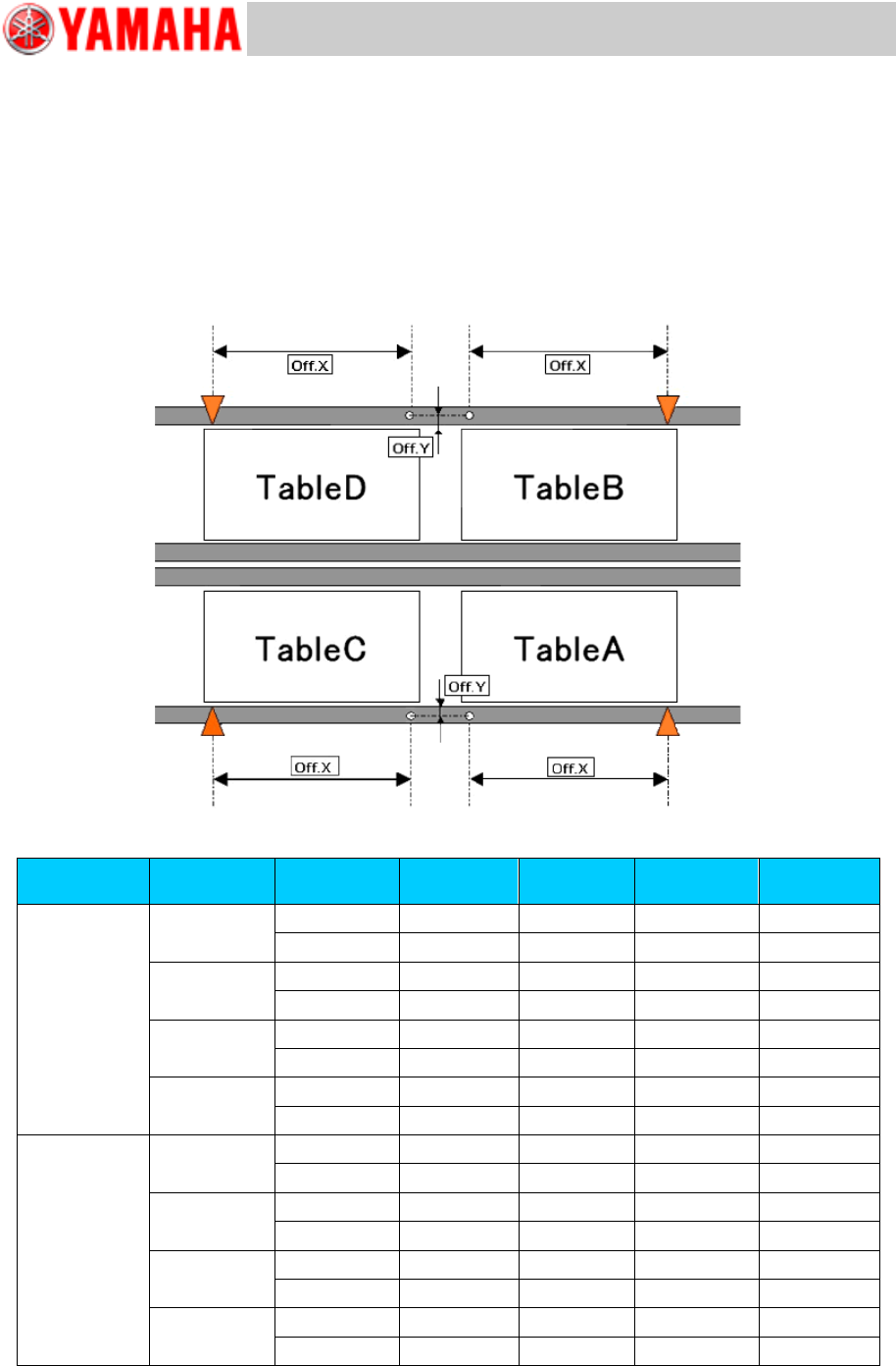
[Relation between the data check datum position and the mark position on the conveyor]
<<YSM40-4>>
Figure 29
Board flow
direction
Table
Datum No.
Offset :X
Offset: Y
Edge
Clamp X
Edge
Clamp Y
Right Left
A
1
182.5
13.5
5
5
2
182.5
-13.5
5
-5
B
1
182.5
13.5
5
5
2
182.5
-13.5
5
-5
C
1
-182.5
13.5
5
5
2
-182.5
-13.5
5
-5
D
1
-182.5
13.5
5
5
2
-182.5
-13.5
5
-5
Left Right
A
1
182.5
13.5
-5
5
2
182.5
-13.5
-5
-5
B
1
182.5
13.5
-5
5
2
182.5
-13.5
-5
-5
C
1
-182.5
13.5
-5
5
2
-182.5
-13.5
-5
-5
D
1
-182.5
13.5
-5
5
2
-182.5
-13.5
-5
-5
Table 5
Service Engineer
Service Information
SI1407002E-000=YSM40_How to change the board flow direction (Tentative measure)
21/24
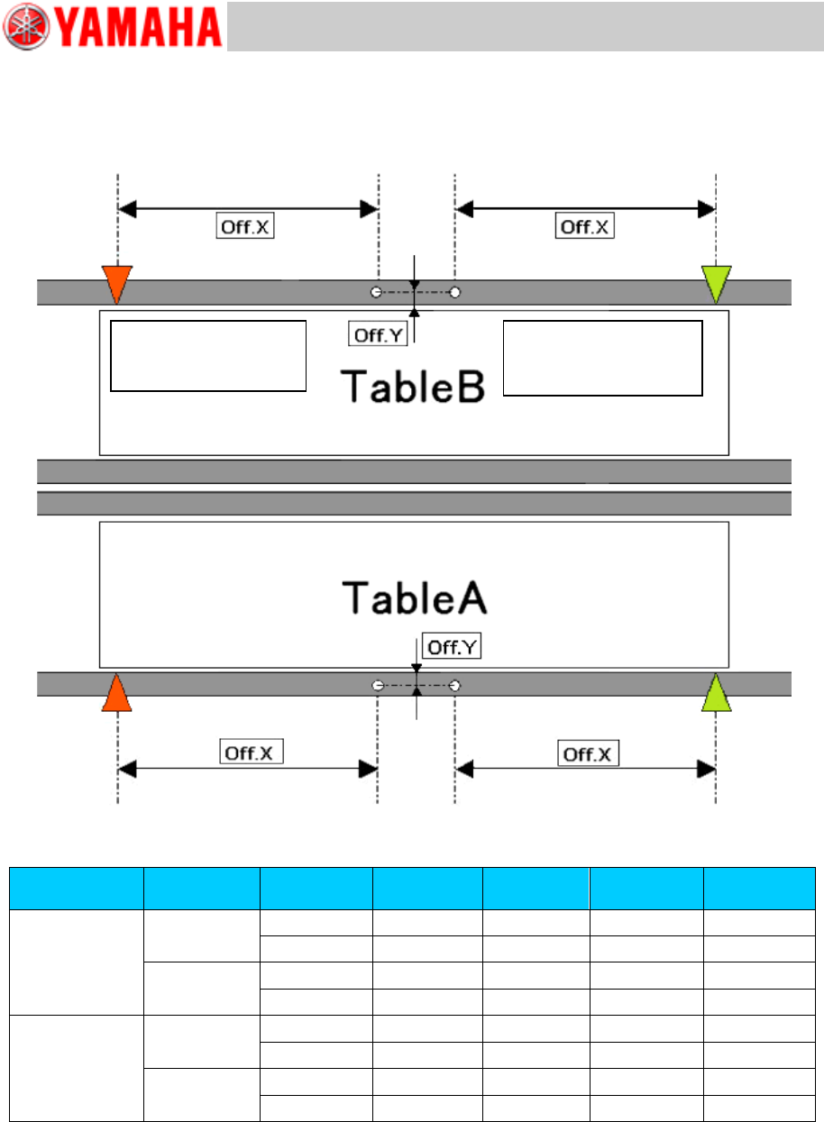
[Relation between the data check datum position and the mark position on the conveyor]
<<YSM40-2>>
Figure 30
Board flow
direction
Table
Datum No.
Offset :X
Offset: Y
Edge
Clamp X
Edge
Clamp Y
Right Left
A
1
-182.5
13.5
5
5
2
-182.5
-13.5
5
-5
B
1
-182.5
13.5
5
5
2
-182.5
-13.5
5
-5
Left Right
A
1
182.5
13.5
-5
5
2
182.5
-13.5
-5
-5
B
1
182.5
13.5
-5
5
2
182.5
-13.5
-5
-5
Table 6
Board flow direction:
Right Left
Data check origin
Board flow direction:
Left Right
Data check origin
Service Engineer
Service Information
SI1407002E-000=YSM40_How to change the board flow direction (Tentative measure)
22/24
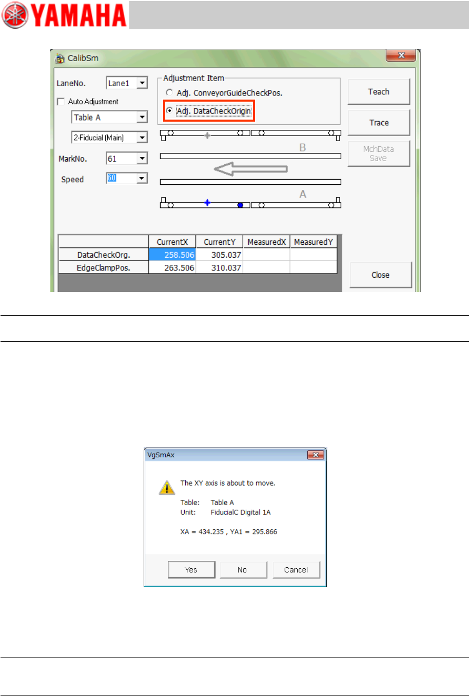
Figure 31
Note:
Use the Database No.61 to recognize the mark on the jig and check the position shift.
1. Tap the [112 Check Conveyor] button on the CalibSm main menu.
2. Select “Adj. Data Check Origin” from “Adjustment Item”.
3. Select the table and the lane number (“Lane No.”) to be used for the adjustment.
* The recognition camera is automatically determined, so you do not need to select it.
4. Tap the [Trace] button to move the camera to the measurement position.
Figure 32
The camera moves to the specified mark position and the mark recognition is performed
automatically, and then it moves to the center of the mark. Save the measured result.
* The Edge clamp position is calculated and saved at the same time.
Note:
If the position is not appropriate, tap the [Teach] button and manually move the axis and perform the
adjustment.
5. Change the setting of “Check Pos” and perform the adjustment for each table.