YSM20&40_how_to_change_directionPDFA.pdf - 第22页
Service Engineer Service Information SI1407002E - 000 =YSM40_How to change the board flow direction (Tentative measure) 22 / 24 Figure 31 Note: Use the Database No.6 1 to recognize the m ark on the jig and check the posi…
Service Engineer
Service Information
SI1407002E-000=YSM40_How to change the board flow direction (Tentative measure)
21/24
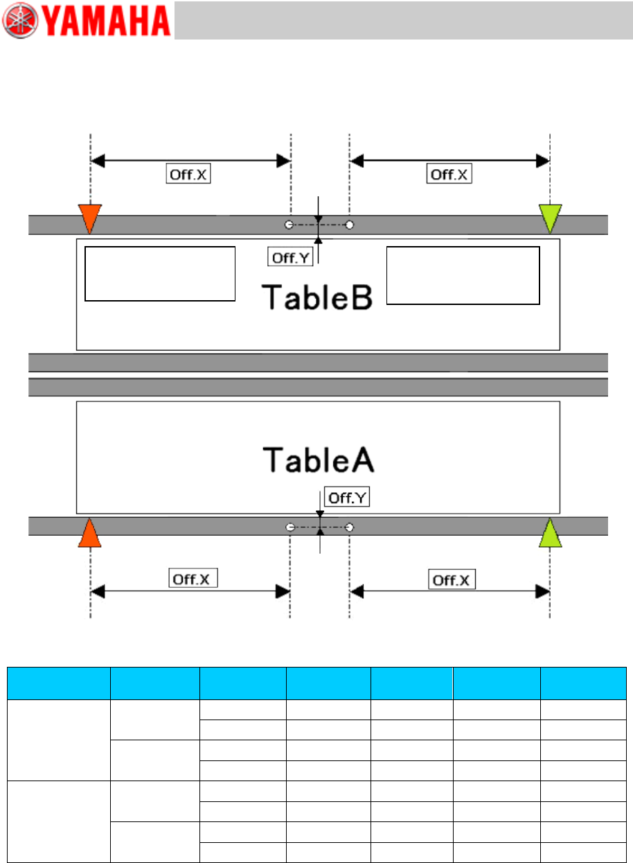
[Relation between the data check datum position and the mark position on the conveyor]
<<YSM40-2>>
Figure 30
Board flow
direction
Table
Datum No.
Offset :X
Offset: Y
Edge
Clamp X
Edge
Clamp Y
Right Left
A
1
-182.5
13.5
5
5
2
-182.5
-13.5
5
-5
B
1
-182.5
13.5
5
5
2
-182.5
-13.5
5
-5
Left Right
A
1
182.5
13.5
-5
5
2
182.5
-13.5
-5
-5
B
1
182.5
13.5
-5
5
2
182.5
-13.5
-5
-5
Table 6
Board flow direction:
Right Left
Data check origin
Board flow direction:
Left Right
Data check origin
Service Engineer
Service Information
SI1407002E-000=YSM40_How to change the board flow direction (Tentative measure)
22/24
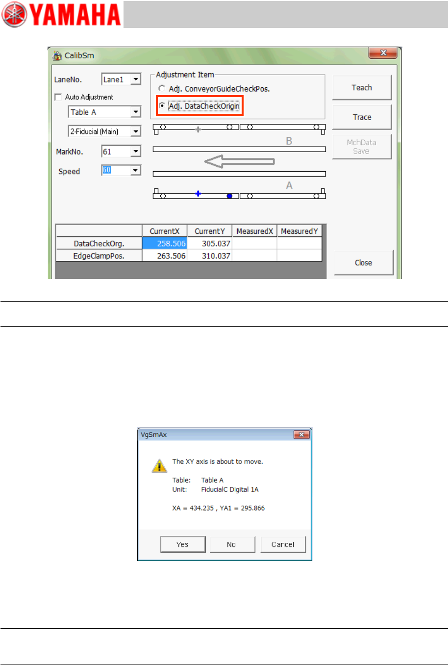
Figure 31
Note:
Use the Database No.61 to recognize the mark on the jig and check the position shift.
1. Tap the [112 Check Conveyor] button on the CalibSm main menu.
2. Select “Adj. Data Check Origin” from “Adjustment Item”.
3. Select the table and the lane number (“Lane No.”) to be used for the adjustment.
* The recognition camera is automatically determined, so you do not need to select it.
4. Tap the [Trace] button to move the camera to the measurement position.
Figure 32
The camera moves to the specified mark position and the mark recognition is performed
automatically, and then it moves to the center of the mark. Save the measured result.
* The Edge clamp position is calculated and saved at the same time.
Note:
If the position is not appropriate, tap the [Teach] button and manually move the axis and perform the
adjustment.
5. Change the setting of “Check Pos” and perform the adjustment for each table.
Service Engineer
Service Information
SI1407002E-000=YSM40_How to change the board flow direction (Tentative measure)
23/24
3.2.3 “Transfer Distance” adjustment
In order to realize the board transfer without stoppers and mounting on large boards in a small
space, YSM40 is equipped with some board sensors.
Adjust the board sensor position precisely, and adjust the “Data Check Origin” position as the
parameter related to transfer distance by the moving distance of the CV-axis.
Note:
Make sure to perform the “Adj. Data Check Origin” adjustment before performing the “Transfer
Distance” adjustment.
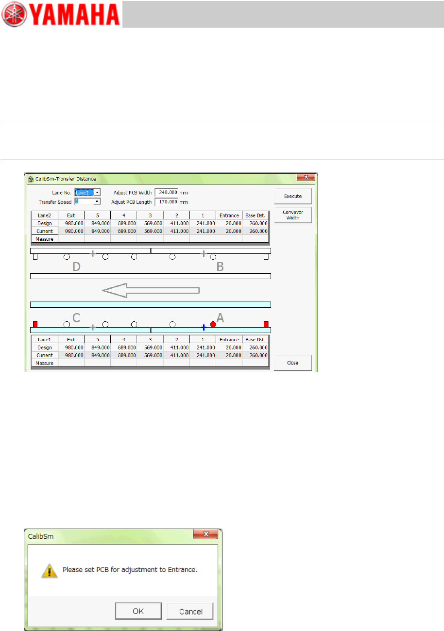
Figure 33
1. Tap the [113 Transfer Distance] button on the CalibSm main menu.
2. Tap the [Conveyor Width] button to change the conveyor width.
Set the conveyor width as follows, as the glass board needs to be set on the conveyor with its short
side parallel to the X-direction for performing the measurement.
・ X: 170mm, Y: 240mm”.
3. Tap the [Execute] button to start the adjustment.
Set the board so that its edge matches to the edge of the Entrance side conveyor.
Set the board as precisely as possible. The adjustment starts when the entrance sensor reacts,
however if the board position is not appropriate, all the positions will be shifted.
Figure 34
4. After the measurement has been completed, save the result.
5. Switch the lane and perform the measurement.