YSM20&40_how_to_change_directionPDFA.pdf - 第9页
Service Engineer Service Information SI1407002E - 000 =YSM40_How to change the board flow direction (Tentative measure) 9/ 24 4. Temporarily attach the br ackets. Attach the brack ets removed in step 2 . Interchange the …
Service Engineer
Service Information
SI1407002E-000=YSM40_How to change the board flow direction (Tentative measure)
8/24
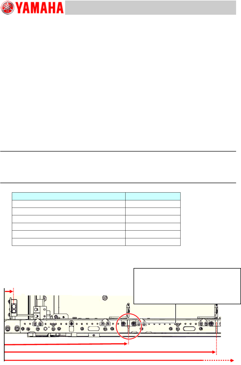
3. Move the fiber sensor (Receiver) position.
Remove the bracket and move the fiber sensor (Receiver) position.
The sensor position shown in the table below is the distance from the conveyor edge on the board
carry-in side.
Measure the distance from the conveyor edge and adjust the sensor position as follows.
<Board flow direction>
From Right to Left: Distance from the right side edge of the conveyor
From Left to Right: Distance from the left side edge of the conveyor
<Note for the work>
Adjust the sensor position by using a tape measure or a ruler.
When moving the sensor, DO NOT PULL the fiber wires. Cut off the cable ties that secure the
fiber wires as needed, and then bundle them again after adjusting the position.
Adjust the fiber sensor (Receiver) position so that it protrudes from the conveyor edge from
1mm to less than 3mm.
If the sensor protrudes 3mm or more from the conveyor edge, it may interfere with the
mounted component.
Caution:
As YSM40 is not equipped with the stoppers on the conveyor, it is possible to perform production even
though the sensor position is slightly shifted.
However if the position is significantly shifted, it may negatively affect the production speed and the
maximum board size that the mounting can be performed.
PCB detection sensor
Position (mm)
Lane 1 Conveyor 1 Entrance Port
18
Lane 1 Conveyor 1 Transit position 1
239
Lane 1 Conveyor 1 Transit position 2
409
Lane 1 Conveyor 2 Transit position 1
567
Lane 1 Conveyor 2 Transit position 3
847
Lane 1 Conveyor 1 Exit Port
978
Table 1
* The position of the Entrance port and the Exit port sensors do not need to be adjusted.
Figure 9
(18)
(409)
(239)
Lane 1 Conveyor 1 Transit position 1
Fix the bracket at the position 239mm (or
closest to 239mm) from the conveyor edge
on the Entrance side.
Service Engineer
Service Information
SI1407002E-000=YSM40_How to change the board flow direction (Tentative measure)
9/24
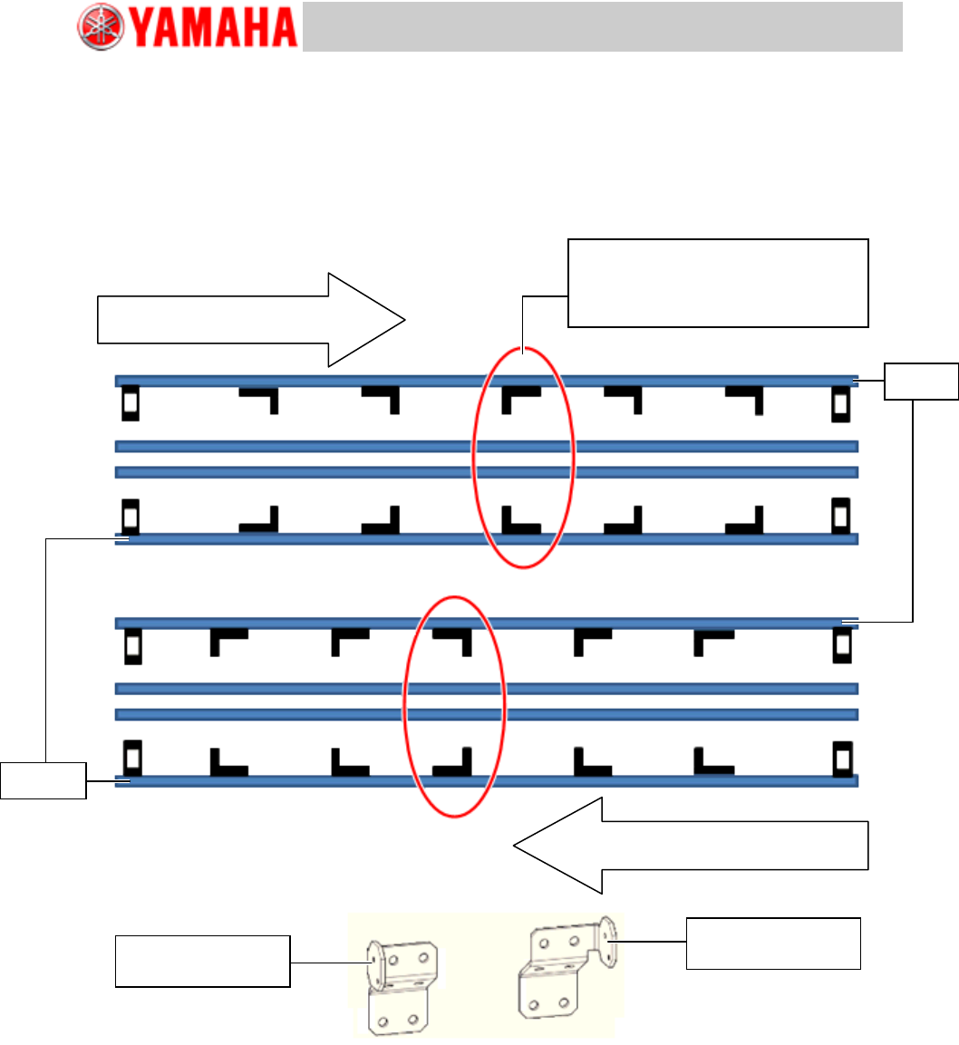
4. Temporarily attach the brackets.
Attach the brackets removed in step 2. Interchange the brackets between the Lane 1 and the Lane
2.
See the figure below for the orientation of the brackets.
As the optical axis position of the sensor will be adjusted later on, attach the brackets only
temporarily.
[Orientation of the brackets]
Figure 10
Board flow direction:
From Left to Right
Board flow direction:
From Right to Left
Set the other type of the bracket of
the brackets on the same lane.
KLF-M912A-01
BRKT., SENSOR
Lane 1
Lane 2
KLF-M912A-51
BRKT., SENSOR
Service Engineer
Service Information
SI1407002E-000=YSM40_How to change the board flow direction (Tentative measure)
10/24
5. Adjust the position of the sensor (Emitter) and route the fiber wire.
Attach the emitter side fiber sensor to the temporarily attached bracket, and adjust the position to
the receiver side sensor that was positioned in step 3.
[Things to bear in mind when routing the fiber sensor]
Avoid the chip dump box position when routing the fiber wire.
Note:
As the chip dump box is removed during the work, if you route the wire to the box position, you will not
be able to set the box later on.
Make sure that the fiber wire does not interfere with the moving parts of the machine (Board
clamp, sideview lighting of the multi camera, blow station, PU-axis and so on).
Fiber wire is basically routed to outside the conveyor. However route it inside the conveyor at
the blow station area as the blow station moves up and down.
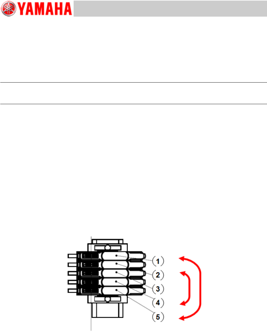
6. Change the positions of the fiber wires at the amplifier.
When changing the board flow direction by the procedure described in this document, the fiber
sensor position is changed. Therefore, the positions of the fiber wires at the amplifier need to be
changed.
Interchange the positions of the following fiber wires.
(1) and (5)
(2) and (4)
(3) does not need to be changed.
Figure 11