N7201A616E00_0317.pdf - 第169页
NPM-W 2 EJM7DE-MB-02O-0 0 2-5-3 -2 8 Remove the PCB support blocks ● Draw out the PCB support b lock. ● Draw it out slowly with both hands. PCB support bloc k(4 plates) ● Push down the lock lever to remove the front bloc…
NPM-W2 EJM7DE-MB-02O-00
OFF
SERVO
2-5-3-1
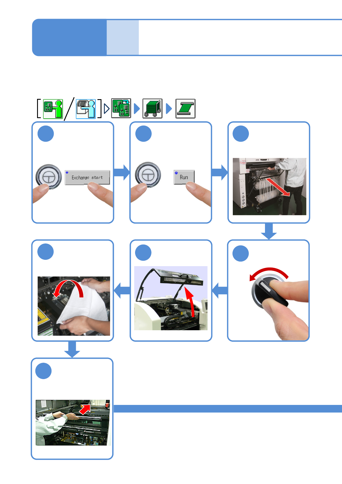
1
ENABLING
After removing
PCBs
2 3
ENABLING
Detach the feeder
cart
(→[Maintenance]
P.3-2)
5
4
7
Cover the line
camera with the
lint-free cloth
6
Hold the feeder
table cover to
the back
Individu-
al
prepara-
tion
Setting support pins 1
Operating procedure
2-5-3
Confirm a
message
Only when the machine and its back side are intended for dual conveyor specifications and feeder cart
specifications, respectively and the machine is in the dual lane mode, remove or attach the PCB support
blocks, starting with the one that is closest to you. Otherwise, start with the front side.
NPM-W2 EJM7DE-MB-02O-00
2-5-3-2
8
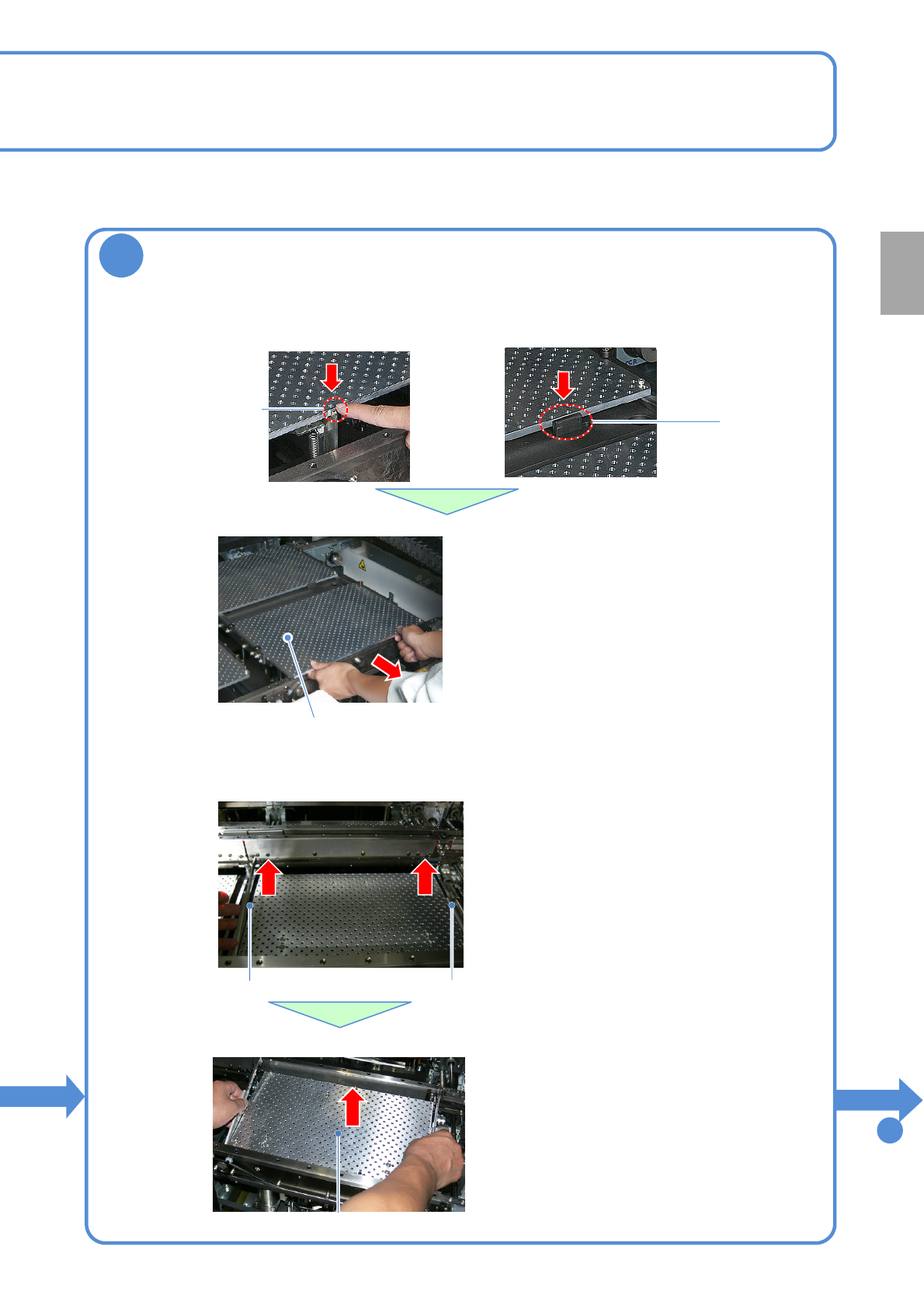
Remove the PCB support blocks
●Draw out the PCB support block.
●Draw it out slowly with both hands.
PCB support block(4 plates)
●Push down the lock lever to remove the
front block in the front.
●Push down the stopper to remove the rear
block in the front.
●The support blocks consist of four split
parts; front, rear, right and left.
●Be careful not to drop a foreign body on
the Multi-recognition camera (LED
lighting) or bump it.
■For single conveyor
■For dual conveyor
Removal lever
■Draw out the PCB support block.
●Draw it out slowly with both hands.
●Be careful not to drop a foreign body on
the Multi-recognition camera (LED
lighting) or bump it.
●The support blocks consist of two split
parts; right and left for each lane.
●Remove both lane as the same way.
PCB support block
●Lift up the right and left levers in the front.
Removal lever
Lock lever
Stopper
To
9
Preparation
NPM-W2 EJM7DE-MB-02O-00
2-5-3-3
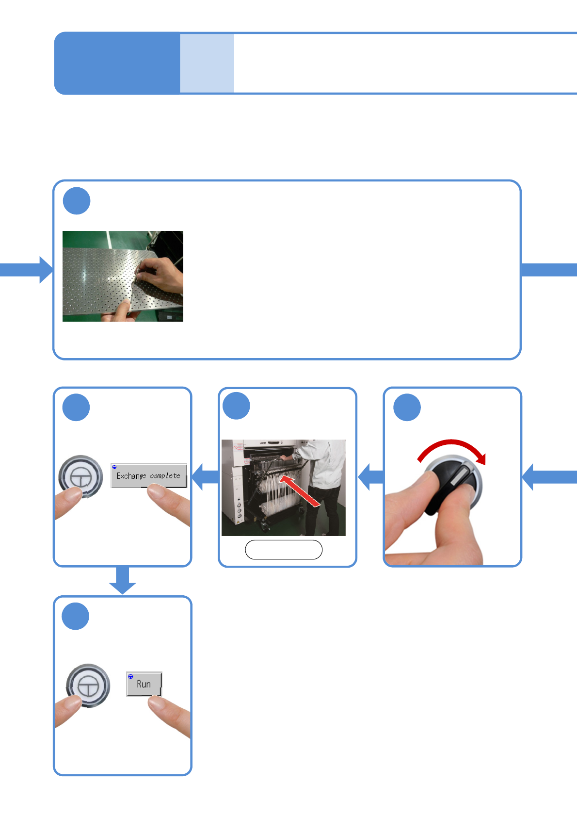
9
Install the support pins into the support block
●Pins should be mounted so as to evenly support an entire PCB.
●Be careful not to bump pins against the components on the
reverse side of PCB.
●Use the support-pin setting jig (option), which helps prevent pins
from being placed in the wrong places.
(Jig: N610131762AC)
Individu-
al
prepara-
tion
Setting support pins 2
Operating procedure
2-5-3
16
17
ENABLING
ENABLING
Attach the feeder
cart
15
Front side
(→[Maintenance] P.3-2)
SERVO
ON
14
●The PCB-support block
moves down.