N7201A616E00_0317.pdf - 第171页
NPM-W 2 EJM7DE-MB-02 O-00 2-5-3 -4 10 Attach the PCB support block as there is no tilt (A void interfering w ith the rail) ■ For single conveyor ■ For dual conveyor ● Adjust the guide pins on the main unit to the holes o…
NPM-W2 EJM7DE-MB-02O-00
2-5-3-3
9
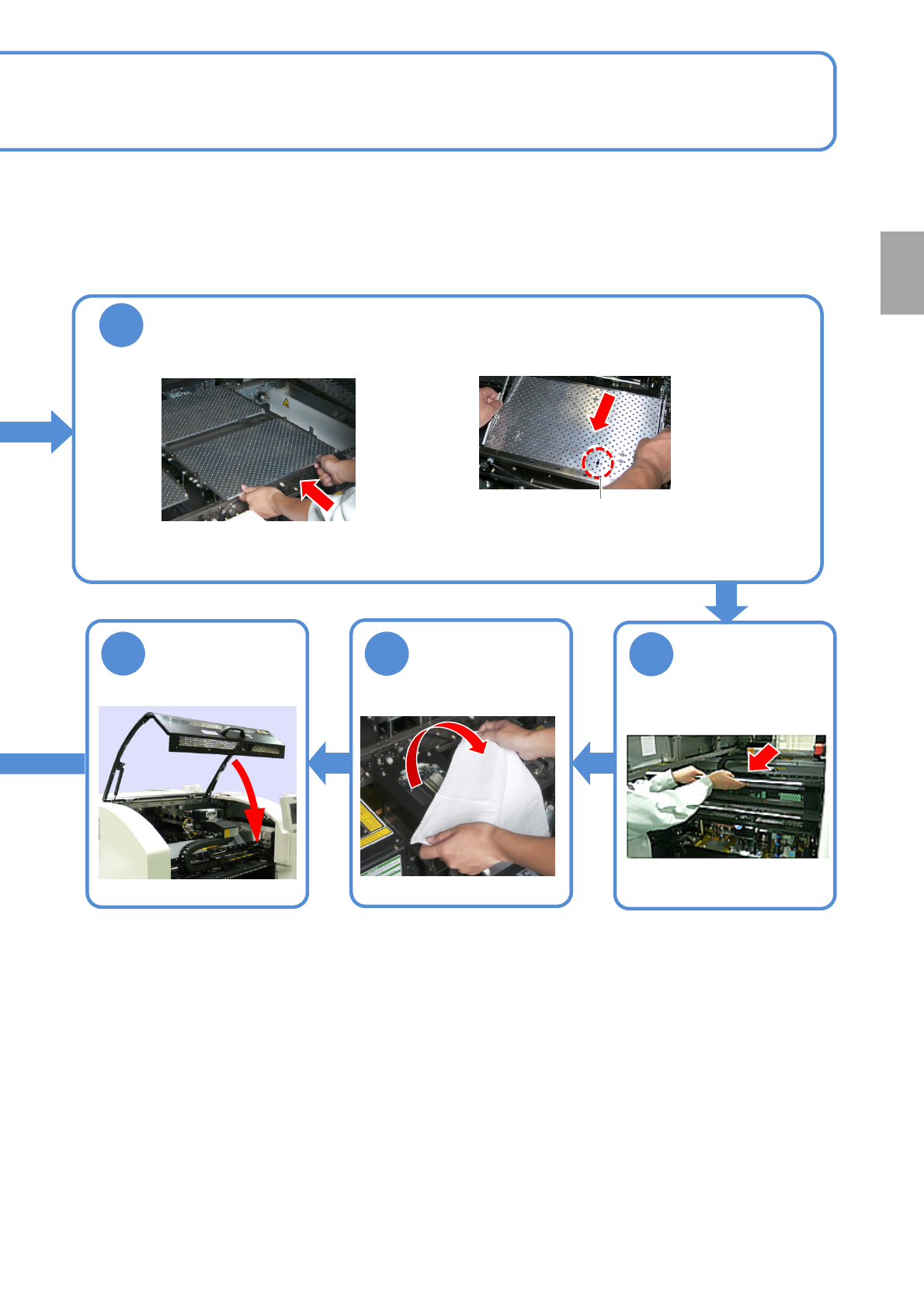
Install the support pins into the support block
●Pins should be mounted so as to evenly support an entire PCB.
●Be careful not to bump pins against the components on the
reverse side of PCB.
●Use the support-pin setting jig (option), which helps prevent pins
from being placed in the wrong places.
(Jig: N610131762AC)
Individu-
al
prepara-
tion
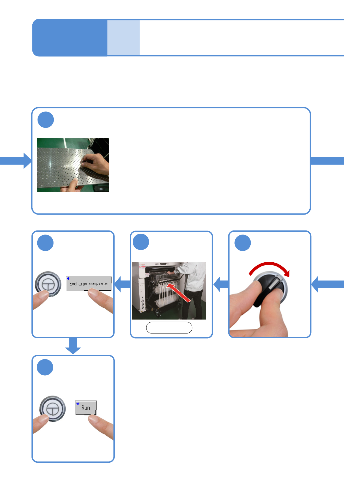
Setting support pins 2
Operating procedure
2-5-3
16
17
ENABLING
ENABLING
Attach the feeder
cart
15
Front side
(→[Maintenance] P.3-2)
SERVO
ON
14
●The PCB-support block
moves down.
NPM-W2 EJM7DE-MB-02O-00
2-5-3-4
10
Attach the PCB support block as there is no tilt (Avoid interfering with the
rail)
■For single conveyor ■For dual conveyor
●Adjust the guide pins on the main unit to
the holes on the PCB support block.
Guide pin
12
Remove the
cloth
13
11
Put the feeder
table cover back
in its place
Preparation
NPM-W2 EJM7DE-MB-02O-00
2-5-4
Individu-
al
prepara-
tion
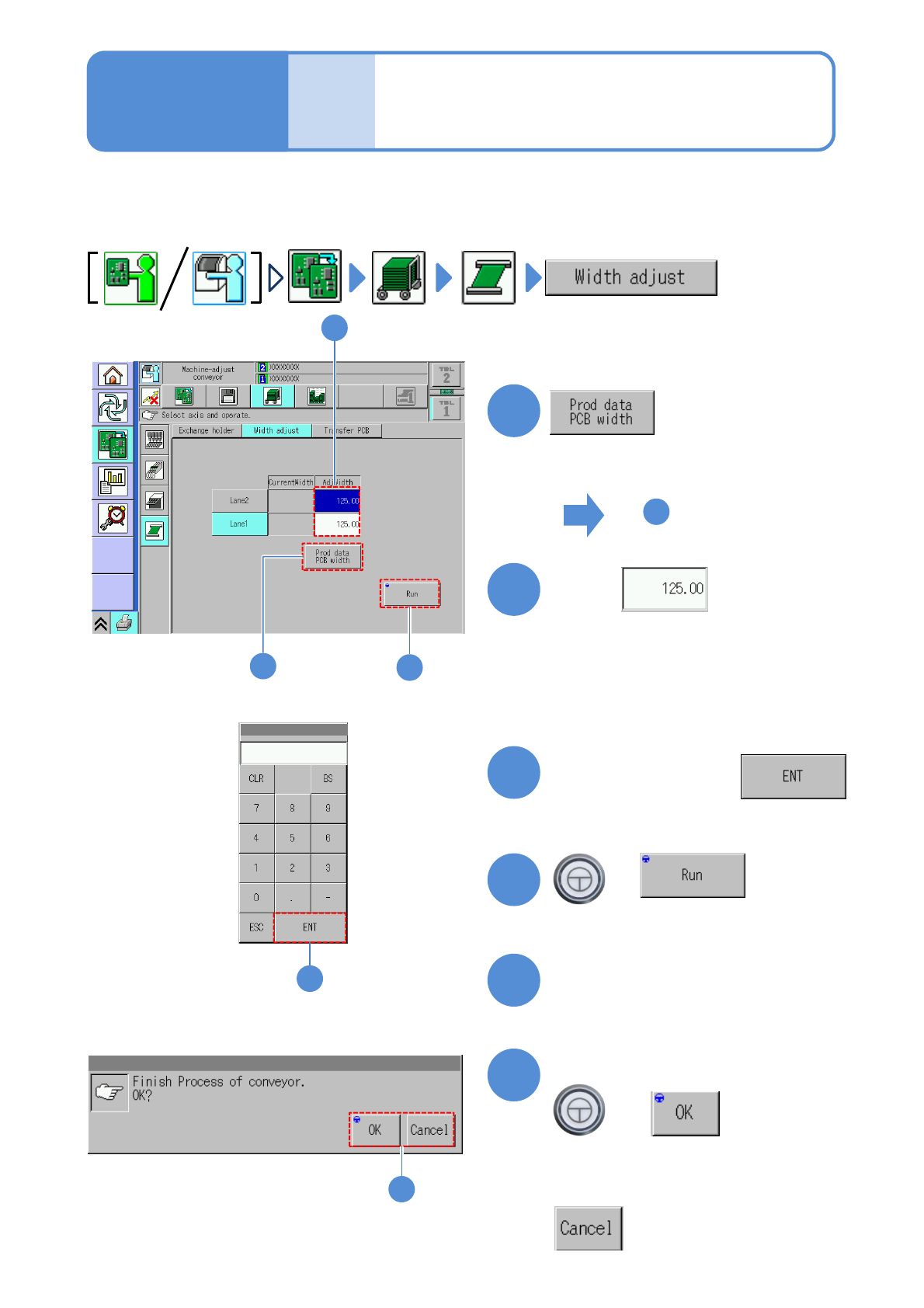
Adjusting transport
conveyor width
Operating procedure
2-5-4
This explains how to adjust the transport conveyor width.
●When you change to smaller PCBs, remove the PCB support blocks and the support pins.
●Avoid changing the conveyor width by rotating the belt by hand. (Otherwise, PCBs may not be detected
with precision)
1
4
1
3
+
(The transport rail width is adjusted)
■To adjust to the PCB width of
production data
■To enter a new PCB width
(The numeric keypad window appears)
Type a PCB width
4
5
Press the next operation button
6
Confirm the message
+
(Switches to the next operation screen)
Touch
4
2
2
6
■To cancel
3
To
(The PCB width of production data is
shown in the numerical field of ‘AdjWidth’)