N7201A616E00_0317.pdf - 第173页
NPM-W 2 EJM7DE-MB-02O-0 0 Individu- al prepara- tion PCB tr anspor t test 2-5-5 Operating procedure 2-5-5 This explains how to test PCB transport on the assumption that you have completed testing on the preceding process…
NPM-W2 EJM7DE-MB-02O-00
2-5-4
Individu-
al
prepara-
tion
Adjusting transport
conveyor width
Operating procedure
2-5-4
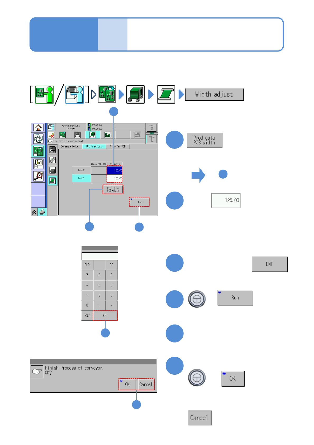
This explains how to adjust the transport conveyor width.
●When you change to smaller PCBs, remove the PCB support blocks and the support pins.
●Avoid changing the conveyor width by rotating the belt by hand. (Otherwise, PCBs may not be detected
with precision)
1
4
1
3
+
(The transport rail width is adjusted)
■To adjust to the PCB width of
production data
■To enter a new PCB width
(The numeric keypad window appears)
Type a PCB width
4
5
Press the next operation button
6
Confirm the message
+
(Switches to the next operation screen)
Touch
4
2
2
6
■To cancel
3
To
(The PCB width of production data is
shown in the numerical field of ‘AdjWidth’)
NPM-W2 EJM7DE-MB-02O-00
Individu-
al
prepara-
tion
PCB transport test
2-5-5
Operating procedure
2-5-5
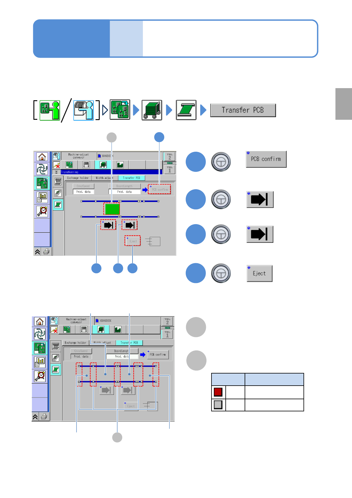
This explains how to test PCB transport on the assumption that you have completed testing on the
preceding processes and that PCBs are present in the upstream process.
●For dual conveyor, you need to choose a lane in advance.
Preparation
B
Sensor
Color Sensor status
*1)
Red ON
Gray OFF
A
PCB transfer position
The location of PCBs on the transport
conveyor is displayed.
2
3
+
+
4
+
(Transported to the 2nd placement
position)
(Transported to the 1st placement
position)
(Transported to the unloading position)
2 3 4
1
1
+
A
*1) This sensor shows the presence /
absence of PCB, with the support
plate being lowered.
B
Loading position
2
nd
placement
position
1
st
placement
position
Unloading
position
(Confirm PCB presence and put it in
transfer ready condition)
NPM-W2 EJM7DE-MB-02O-00
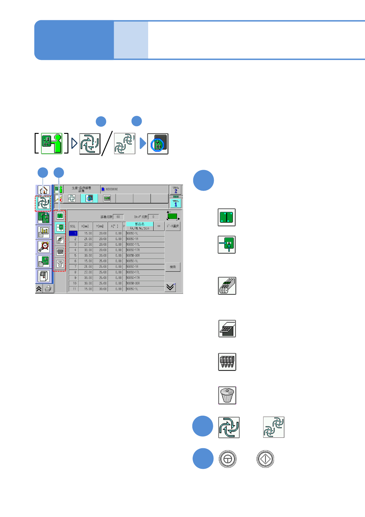
Preparation: do steps through in P.3-1-1-1,P.3-1-1-2.
1
4
2
1
Specify a target for placement
1
3
+
(Production starts under the specified
conditions)
■To specify by the pattern
■To specify by the placement point
■To specify by the component
(intelligent feeder)
■To specify by the component
(tray feeder)
■To specify by the head
■To cancel selection
(→P.2-5-6-2)
(→P.2-5-6
-3)
(→P.2-5-6
-4)
(→P.2-5-6
-5)
(→P.2-5-6
-6)
(→P.2-5-6
-6)
2-5-6-1
2
Individu-
al
prepara-
tion
Placement specification 1
(conditional placement)
Operating procedure
2-5-6
or
A target for placement is specified for production in the unit of patterns or placement points.
Before starting production, using a particular component or block, run a trial to check the placement condition.
For a placement check based on conditional placement, perform the following steps.
For dual conveyor, you can set it per lane by changing the lane.
Inspection head-equipped equipment does not support solder and component inspections during the conditional
placement process.