N7201A616E00_0317.pdf - 第174页
NPM-W 2 EJM7DE-MB-02 O-00 Preparation: do steps through in P.3-1-1-1,P.3- 1-1-2. 1 4 2 1 Specify a target for placement 1 3 + (Production starts unde r the specified conditions) ■ To specify by the pattern ■ To specify b…
NPM-W2 EJM7DE-MB-02O-00
Individu-
al
prepara-
tion
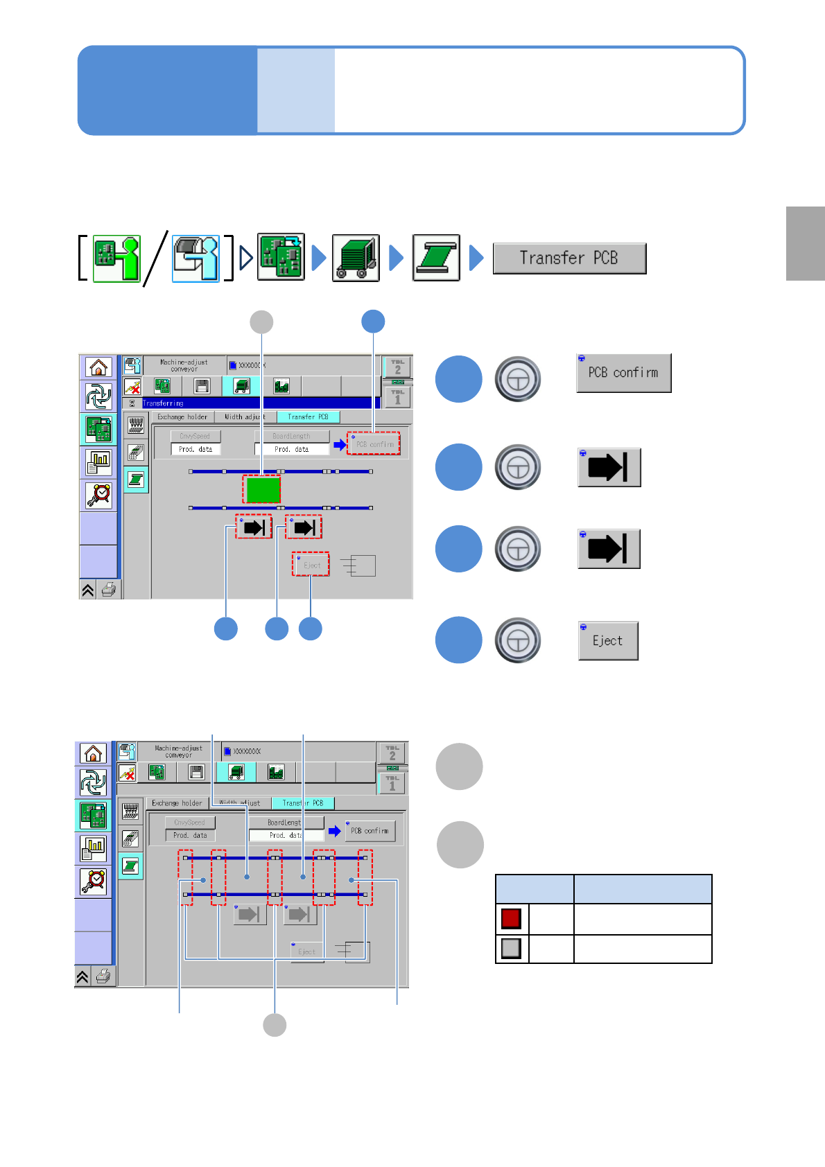
PCB transport test
2-5-5
Operating procedure
2-5-5
This explains how to test PCB transport on the assumption that you have completed testing on the
preceding processes and that PCBs are present in the upstream process.
●For dual conveyor, you need to choose a lane in advance.
Preparation
B
Sensor
Color Sensor status
*1)
Red ON
Gray OFF
A
PCB transfer position
The location of PCBs on the transport
conveyor is displayed.
2
3
+
+
4
+
(Transported to the 2nd placement
position)
(Transported to the 1st placement
position)
(Transported to the unloading position)
2 3 4
1
1
+
A
*1) This sensor shows the presence /
absence of PCB, with the support
plate being lowered.
B
Loading position
2
nd
placement
position
1
st
placement
position
Unloading
position
(Confirm PCB presence and put it in
transfer ready condition)
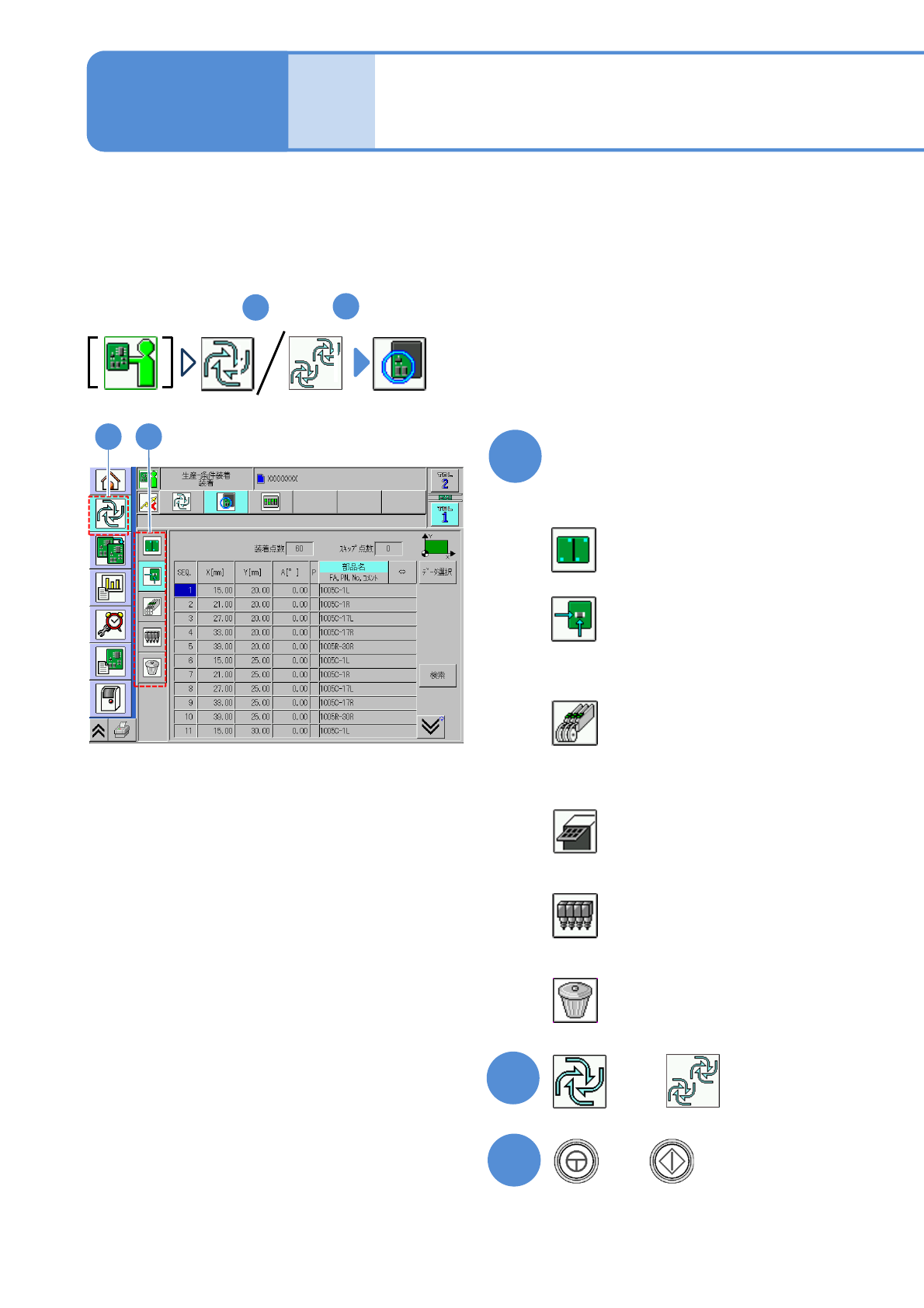
NPM-W2 EJM7DE-MB-02O-00
Preparation: do steps through in P.3-1-1-1,P.3-1-1-2.
1
4
2
1
Specify a target for placement
1
3
+
(Production starts under the specified
conditions)
■To specify by the pattern
■To specify by the placement point
■To specify by the component
(intelligent feeder)
■To specify by the component
(tray feeder)
■To specify by the head
■To cancel selection
(→P.2-5-6-2)
(→P.2-5-6
-3)
(→P.2-5-6
-4)
(→P.2-5-6
-5)
(→P.2-5-6
-6)
(→P.2-5-6
-6)
2-5-6-1
2
Individu-
al
prepara-
tion
Placement specification 1
(conditional placement)
Operating procedure
2-5-6
or
A target for placement is specified for production in the unit of patterns or placement points.
Before starting production, using a particular component or block, run a trial to check the placement condition.
For a placement check based on conditional placement, perform the following steps.
For dual conveyor, you can set it per lane by changing the lane.
Inspection head-equipped equipment does not support solder and component inspections during the conditional
placement process.
NPM-W2 EJM7DE-MB-02O-00
2
1
1 2
Select a pattern
●Multiple patterns are selectable.
3
3
●Deselected by pressing the button
again.
E FC D I
2-5-6-2
A
E
F
G
B
C
D
I
J
H
PatternPiece
The total number of patterns.
SkipPiece
The total number of specified patterns
to be skipped.
No.
The pattern ID number.
ORG.X/ORG.Y
The X/Y coordinates of the origin
pattern.
BAD.X/BAD.Y
The X/Y coordinates of bad patterns.
R
The pattern developing angle number.
PK
The pattern number.
H
Run search by entering a pattern
number with the numeric keypad.
Displays the ROT definition window.
GK
The group number.
Specify by the pattern
J
A GB
Preparation