N7201A616E00_0317.pdf - 第277页
NPM-W 2 EJM7DE-MB-04O-0 0 4-1-2 -2 ■ Ty p e 2 Mainly for the purpose of making the length of produc tion line shorter, any ejection convey or that performs reload operation or reworks PCBs will not be placed in the line.…
NPM-W2 EJM7DE-MB-04O-00
System configuration
Operating procedure
4-1-2
Over-
view
4-1-2-1
It describes the standard configuration of inspection head (component inspection)-installed NPM-W2 system
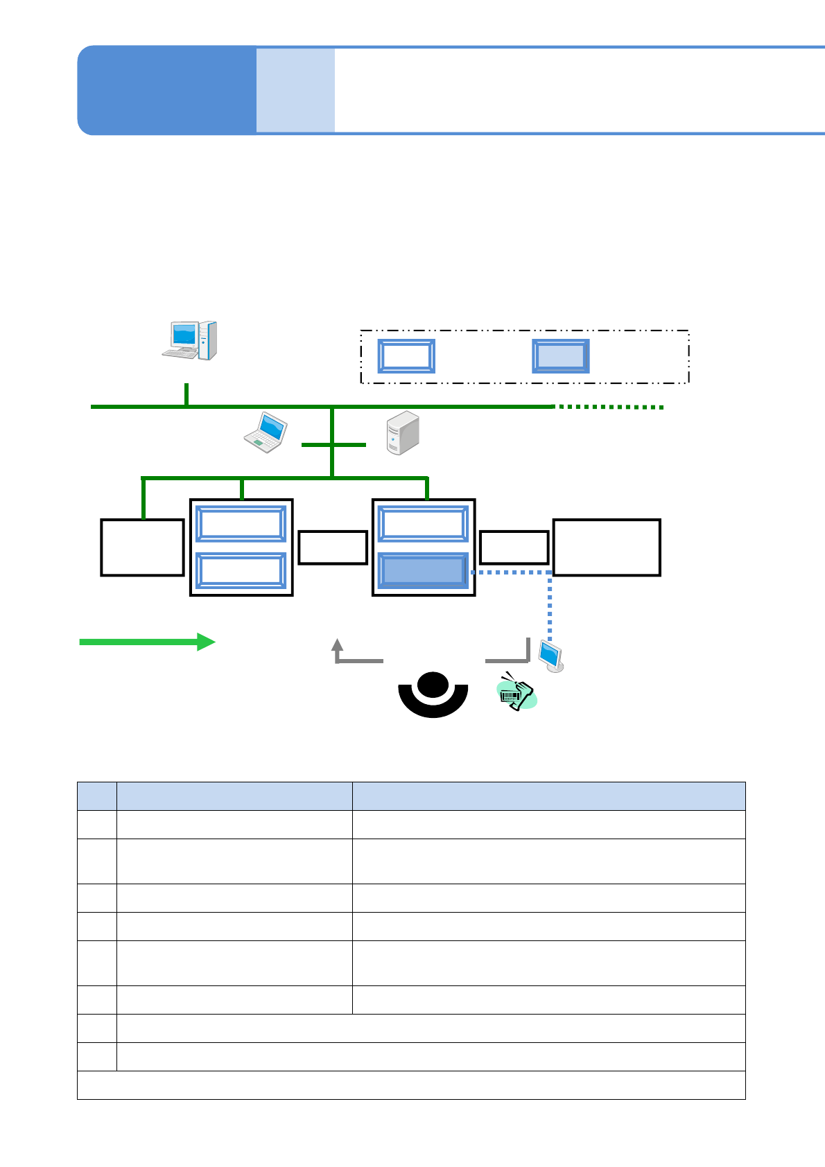
■Type 1
Place a reload conveyor in front of the machine equipped with the inspection head (component inspection), or
place an ejection conveyor just behind the machine equipped with the inspection head (component
inspection).
●Reload conveyor: Reloads reworked PCBs.
●Ejection conveyor: Performs tasks, such as locating a defect/reworking a PCB/registering the PCB for
reloading, in the case a component is rejected at inspection.
NPM-W2
Screen
printer
Reflow
NPM-W2
Reload conveyor
Ejection
conveyor
Barcode scanner
(Reloading of
PCB)
Option display
LWS LNB
(Flow of PCB)
DGS
Placement
head
Inspection head
(component
inspection)
No.
Name Explanation
1 DGS (Data Generation System) Newly creates or edits production data.
2 LNB (Line Network Box)
Saves production information obtained from NPM-W2.
(e.g., inspection result information)
3 LWS (Line Work Station) Edits and adjusts (tunes) inspection data during production.
4 Option display
*1)
Displays defective areas for ease of rework.
5 Barcode scanner
*2)
Reads a barcode on a defective PCB when the PCB is
reloaded via the reload conveyor after rework.
6 Reload/Ejection conveyor
*1)
Reloads reworked PCBs/removes defective PCBs.
*1) Devices to be prepared by you
*2) NPM-W2 standard optional devices (only wired type can be used)
For reloading a reworked PCB, devices 4, 5, and 6 above are required. (→P.4-5)
■Explanation of major peripheral devices (Phrases/words in this table will be used
in an abbreviated form in the rest of the manual)
NPM-W2 EJM7DE-MB-04O-00
4-1-2-2
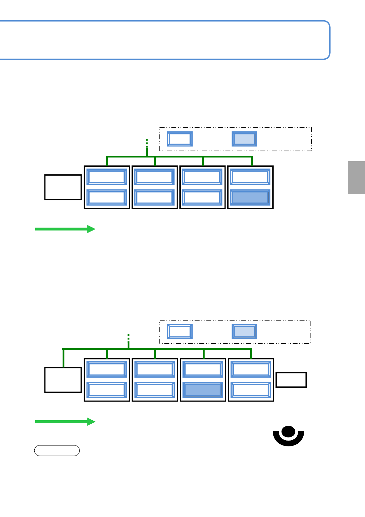
■Type 2
Mainly for the purpose of making the length of production line shorter, any ejection conveyor that performs
reload operation or reworks PCBs will not be placed in the line.
●In the case where the machine equipped with an inspection head for solder inspection use is placed first in
the production line (→P.5-1-2)
NPM-W2
Screen
printer
NPM-W2
(PCB flow)
Placement
head
Inspection head
(component
inspection)
NPM-W2 NPM-W2
■Type 3
The machine equipped with the inspection head (component inspection) will be placed last but one in the
production line (the second machine from the last one).
●Components that need to be checked for foreign bodies shall be placed as follows, provided that the
components include both reel and tray types.
However, you cannot conduct post-placement component inspection or reload operation in downstream
processes after a component is placed.
●In the case where the machine equipped with an inspection head for solder inspection use is placed first in
the production line (→P.5-1-2)
NOTICE
Reel
NPM-W2
Screen
printer
NPM-W2
Ejection conveyor
(PCB flow)
Placement
head
Inspection head
(component
inspection)
NPM-W2
Tray
NPM-W2
(Removal/rework of PCB)
●To rework or remove a PCB using the ejection conveyor, it is necessary to set up the position of the
ejection conveyor placed in the line with LNB. Please use “LNB configuration information” of LNB for setting
“Ejection conveyor” to the position of the ejection conveyor in the line.
For information on how to set up, (→ Chapter 4 in [LNB] operating instruction)
Component
inspection
NPM-W2 EJM7DE-MB-04O-00
4-1-3-1
Inspection
specifications
Operating procedure
4-1-3
■Component
Camera resolution of 18μm (type A): 0603 chip or larger, QFP with the lead pitch of 0.4mm or more
Camera resolution of 9μm (type B): 0402chip or larger, QFP with the lead pitch 0.3mm or more
■Component size
Chip component: 10,000 points
■Number of available inspection points
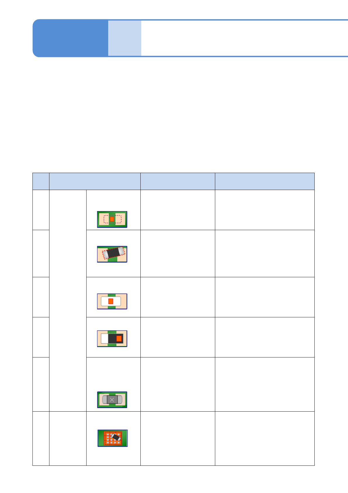
■Inspection type
No.
Inspection type Inspection target Criterion
1
Post-
placement
inspection
Component
presence/absence
・There is no component
at the placement
position
・Judged as conforming if a PCB is
not displayed in color, or if a
component is displayed in color
2
Displacement ・The component
placement position is
shifted
・The component
placement angle is
shifted
・Judged as conforming if the shift
amount of the measured
electrode or component position
is within the set range
3
Flip over
*1)
・The placed component
is flipped.
・The placed component
is in a tombstoning
posture.
・Judged as nonconforming if the
reverse side or side of a
component is displayed in color
4
Wrong polarity
*2)
・The orientation of the
placed component is
incorrect
(for components with
olarity)
・Judged as conforming if a
component’s polarity is displayed
in color
5
Different
component
detection
(currently unused)
・The placed component
is different
・Judged as conforming if a
component is within the judgment
value in the template matching.
6
Pre-
placement
inspection
Foreign body
detection
・There is a dropped part
under the placement
component
(for components to be
placed by the
inspection-head-
installed machine)
・Judged as conforming if nothing
other than a PCB is displayed in
color
(excluding the already-placed
component area)
Over-
view
Square chip, SOP, QFP, BGA, CSP, aluminum electrolytic capacitor, volume, trimmer, coil, connector,
network resistance, transistor, diode, inductor, tantalum capacitor, cylinder chip