N7201A616E00_0317.pdf - 第280页
NPM-W 2 EJM7DE-MB-04O-0 0 Produc- tion configu- ration Setting soft s witc h Operating procedure 4-2-1 A This s ection des cribes component ins pection by th e PCB insp ection head, and parameter s ettings required to re…
NPM-W2 EJM7DE-MB-04O-00
4-1-3-2
1)
For such a square chip resistor as has different colors on its front and back, the inspection for flip-over
can be set.
2)
The contrast of the polarity mark shall be clear. No dirt or blur. And also make sure that color or
brightness variability shall be narrow, and, as for IC, polar shape can be recognized by the image and
remains unchanged.
●The color and inspection area to be used for each inspection are set through the use of the pre-captured
image.
●For the PCB color, each color of PCB, solder, land, silk, and others is predetermined.
●For the placed component, if its color is missing by being shaded by its adjacent ones, the inspection
process may not be possible. And if there is no difference in color and brightness between PCB and
components, or if there are any variations in color and brightness due to the materials of PCB/components
or warp/deformation in PCB, the inspection process may not be possible. Also, please avoid installing the
machine in direct sunlight or near strong light.
Component
inspection
NPM-W2 EJM7DE-MB-04O-00
Produc-
tion
configu-
ration
Setting soft switch
Operating procedure
4-2-1
A
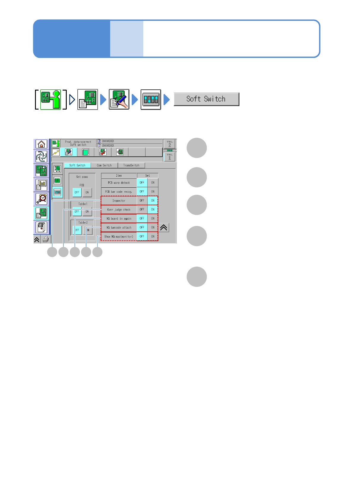
This section describes component inspection by the PCB inspection head, and parameter settings
required to reload repaired PCBs.
A
The inspection function is enabled.
Inspector
B C D E
B
The over judgment input function is enabled.
Over judge check
C
The function used to reload the defective
PCBs that have been repaired is enabled.
NG PCB in again
D
The operation used to affix a barcode to
the reloaded PCBs is enabled.
NG barcode attach
E
The location and image of the rejected
component on a PCB are displayed.
Your own monitor and mouse need to
have been connected to the inspection
box.
Show NG map (monitor)
4-2-1
NPM-W2 EJM7DE-MB-04O-00
Overview
Operating procedure
4-3-1
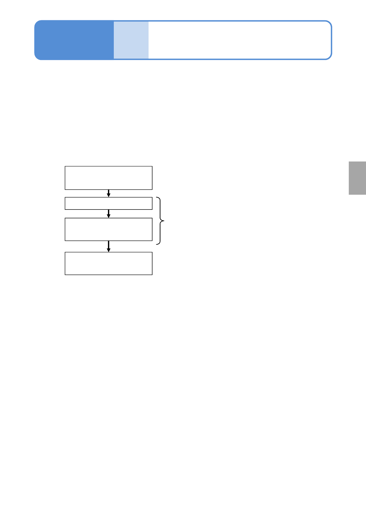
■Teaching flow
Creating the production data
(inspection FOV data)
Loading the production data
Capturing the images of
teaching PCBs
Setting with the 2D inspection
editor
Created by NPM-DGS
Edited with NPM-DGS
Operated by the machine
Produc-
tion data
and
teach
4-3-1
This section describes teaching intended for component inspection.
To judge whether any components are on board or not, NPM-DGS is used for teaching of the colors of both
PCB and component. Before a judgment is formed, the inspection head captures the image of a PCB in the
case of teaching of the PCB color and the image of on-board components in the case of teaching of the on-
board component color.
Production data after inspection is edited by [2D inspection editor] of the NPM-DGS.
●It is possible to configure [Setting of soft switches] only, as far as the NPM-W2 equipped with the
inspection head is concerned.
The mouse, keyboard, or monitor being connected to NPM-W2 or the inspection BOX cannot be used for
editing production data.
Component
inspection