N7201A616E00_0317.pdf - 第303页
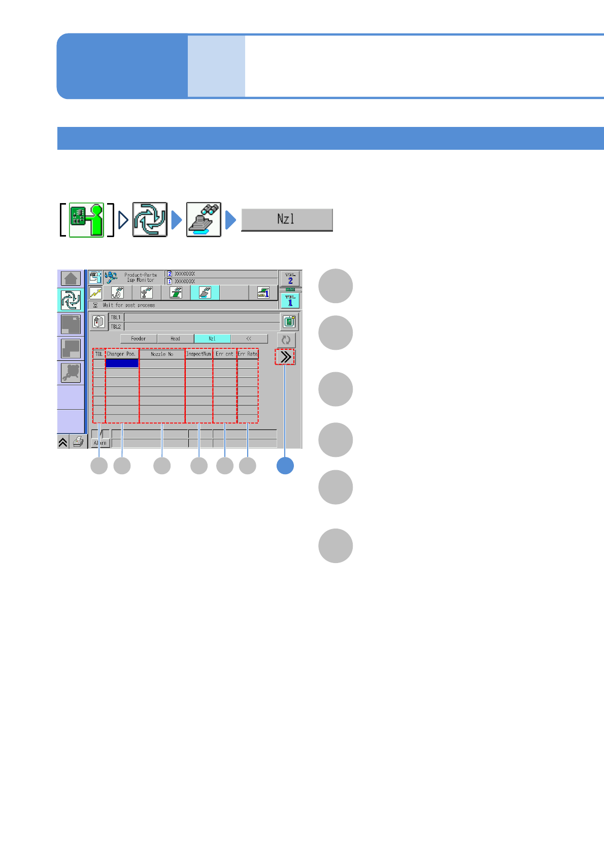
NPM-W 2 EJM7DE-MB-04 O-00 4-4-3 -12 1 C D G H E F I J A B TBL (table) B A (Displays detailed error information) Returns to the previous screen. D C E F G H I J The number of flip-over inspection errors. The number of for…
NPM-W2 EJM7DE-MB-04O-00
A
TBL (table)
B
Changer Pos.
A C
4-4-3-11
B D E F
E
Err cnt
F
Err Rate
D
InspectNum
C
Nozzle No.
1
Inspection monitor 6
Operating procedure
4-4-3
Produc-
tion
Position of nozzles inside the nozzle
changer.
In the cases such as these, where certain nozzles produce a high concentration of defects, the components
judged as defective are checked on a per-nozzle basis so that they are utilized to identify and take measures
against the causes of defects.
The number of inspected components
judged as defective.
(Err cnt / InspectNum) × 100 (%)
Nozzle
NPM-W2 EJM7DE-MB-04O-00
4-4-3-12
1
C
D
G
H
E
F
I
J
A
B
TBL (table)
B
A
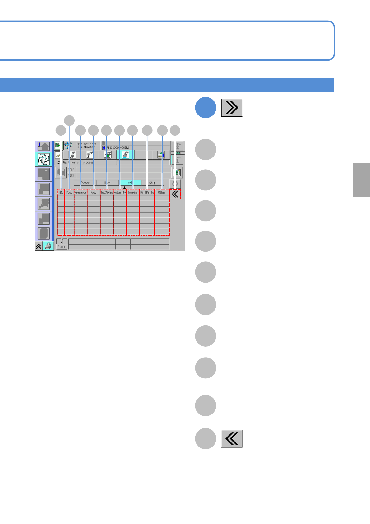
(Displays detailed error information)
Returns to the previous screen.
DC E F G H I J
The number of flip-over inspection errors.
The number of foreign body inspection
errors.
The number of different component
inspection errors.
(Currently not in use)
The number of polarity inspection errors.
The number of other errors.
The number of presence/absence
inspection errors.
The number of displacement inspection
errors.
Nozzle position in the placement head.
Foreign body
Different component
Flip-over
Presence/absence
Position
Polarity
Other
Position
Component
inspection
NPM-W2 EJM7DE-MB-04O-00
Wrong judgment input
screen 1
Operating procedure
4-4-4
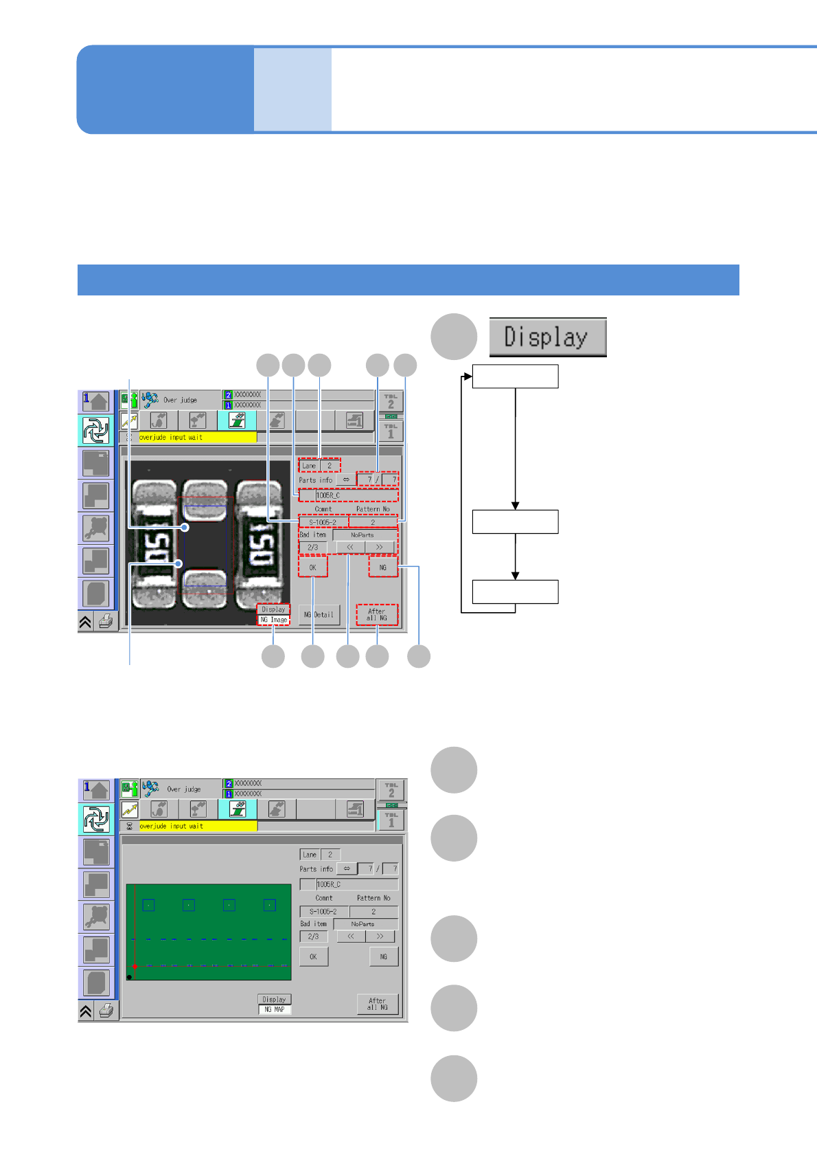
The wrong judgment screen is displayed when an inspection result turns out to be defective.
The following screen will not be displayed and a defective PCB is unloaded as it is if the soft
switch (→P.4-2-1) for [Over judge check] is OFF.
●Visually check any inspection-NG location displayed on the screen and set it as either nonconforming or
conforming (misjudgment) before resuming production.
A
B
E
Comment
F
Pattern No
C
Lane
D
Comp info
Name of placement component (part name).
■NG image display
■NG MAP display
(Only for component
inspection)
Displays the image at the
time of conforming judgment.
The image of a conforming
item is automatically saved
to LNB if the target
component is judged as OK.
Lane No
Blue frame in the image:
Component position
●When APC is available
Light blue frame in the image
Component position (after APC correction)
Red frame in the image:
Component misalignment tolerance
(when position inspection is enabled)
G
CDE F
H IJA
B
OK Image
(Component inspection /
solder inspection)
Displays the image that
makes a nonconforming
judgment at the moment.
NG image
(Component inspection /
solder inspection)
Displays any NG location on
PCB on the map.
NG MAP
Produc-
tion
4-4-4-1
Over judgment input
Nominator: The order of inspection NGs.
Denominator : The total number of
inspection NGs.
Nominator / Denominator