N7201A616E00_0317.pdf - 第310页
NPM-W 2 EJM7DE-MB-04 O-00 Ov er view Operating procedure 4-5-1 Defec- tive PCB process 4-5-1 ■ Defective PCB process Defective PCB p rocess refers to a ser ies of actions used for PC Bs judged as defec tive by the inspec…
NPM-W2 EJM7DE-MB-04O-00
Finishing production
Operating procedure
4-4-5
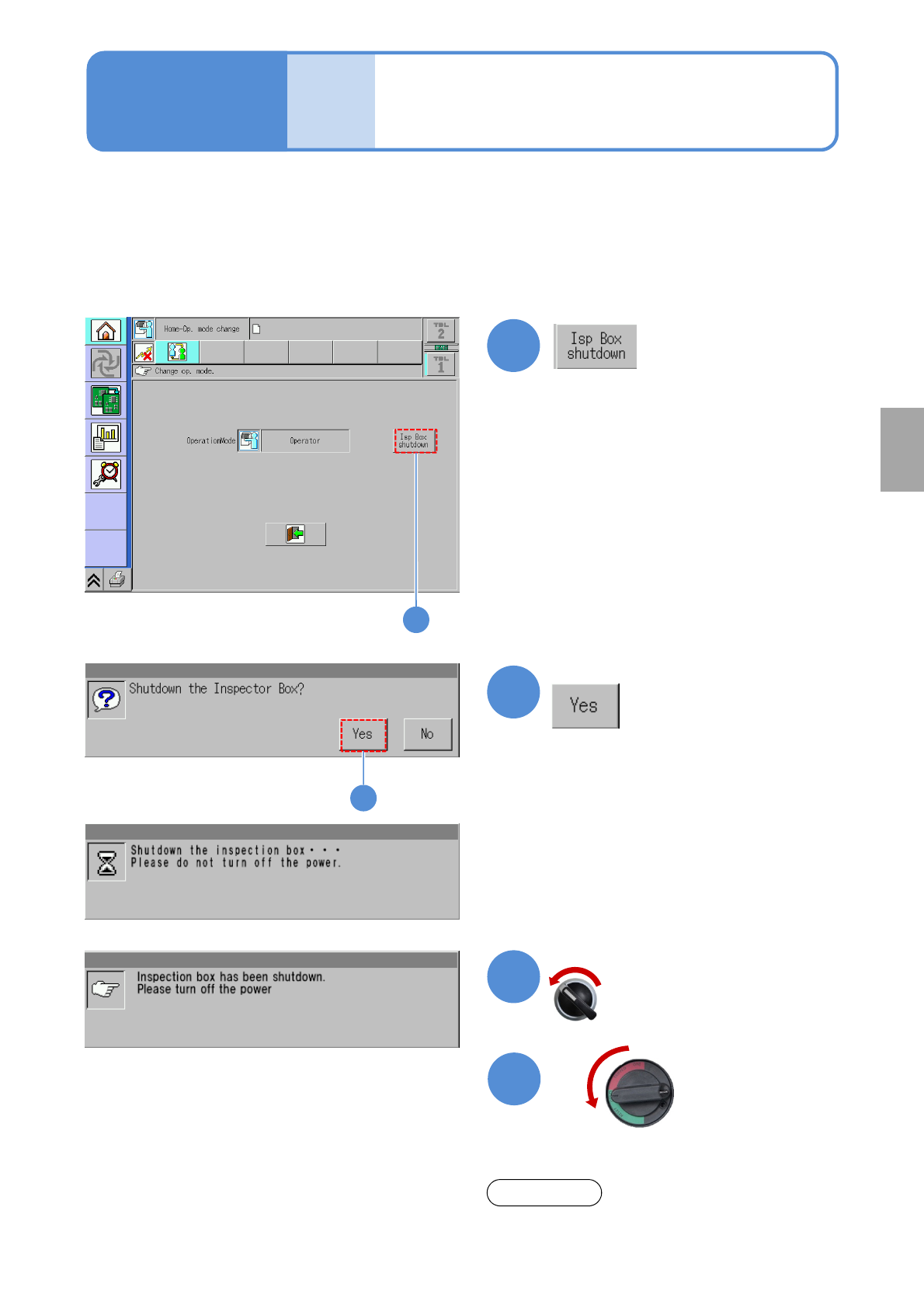
Since the inspection box (PC and UPS—Uninterruptible Power Supply) is connected to NPM-W2 with the
inspection head, shut down the inspection box before turning off the power to the machine.
●Failing to do so may shorten a battery life of UPS or disable communication with the inspection box next
time.
●When communication with the inspection box cannot be established, shut down the machine and wait for
one minute or more before restarting the machine.
Produc-
tion
4-4-5
1
2
2
3
4
OFF
1
Confirm the message
Confirm the message
Even though the background of the message blinks, it is
not machine trouble.
NOTE
Servo switch OFF
Component
inspection
NPM-W2 EJM7DE-MB-04O-00
Overview
Operating procedure
4-5-1
Defec-
tive PCB
process
4-5-1
■Defective PCB process
Defective PCB process refers to a series of actions used for PCBs judged as defective by the inspection head.
●Removal of PCBs having a defective inspection result.
●Repair work (elimination of foreign body, etc.).
●Reloading and placement of repaired PCBs.
NPM-W2 equipped with an inspection head (component inspection) makes a component inspection prior to
placement of a shield case (*1) and a foreign body inspection prior to BGA placement (*2), and, once a PCB
is detected to be defective in a certain spot, is designed to unload the PCB without placing any components at
the spot.
■Defective PCB process methods
The defective PCB process is operated in two different manners --- one uses the barcode scanner, and the
other one does not use the barcode scanner.
■Operation with the barcode scanner (→P.4-5-2)
●When a defective PCB is removed, a reload barcode is attached and read by the barcode scanner.
●When a defective PCB is repaired and then reloaded, the barcode scanner reads its reload barcode.
●If re-inspection of the defective spot on the loaded PCB reveals no problem, the screen to confirm the
placement of the yet-to-be placed component appears. And select “Place it” on the screen to place the
component on the PCB.
●The following two setups are required to carry out processing of defective PCBs.
1. Set up reload IDs with LNB. (→ Chapter 4 ‘PCB ID Setting’ in [LNB] Operating Instructions)
2. Set up soft switches on equipment with the inspection head (component inspection). (→P.4-2-1)
■Operation without the barcode scanner (→P.4-5-3)
●The barcode scanner cannot be used to remove a defective PCB.
●The barcode scanner cannot be also used even to repair and reload a defective PCB.
●If re-inspection of a defective spot on a loaded PCB reveals no problem, the screen to confirm the
placement of a component, which is yet to be placed, appears. And select “Place it” on the screen to place
the component on the PCB.
●In this operation, such communication functions as “Transfer of bad mark recognition results,” “Transfer of
PCB warpage info,” “APC function,” and “Automatic product changeover function” cannot be used.
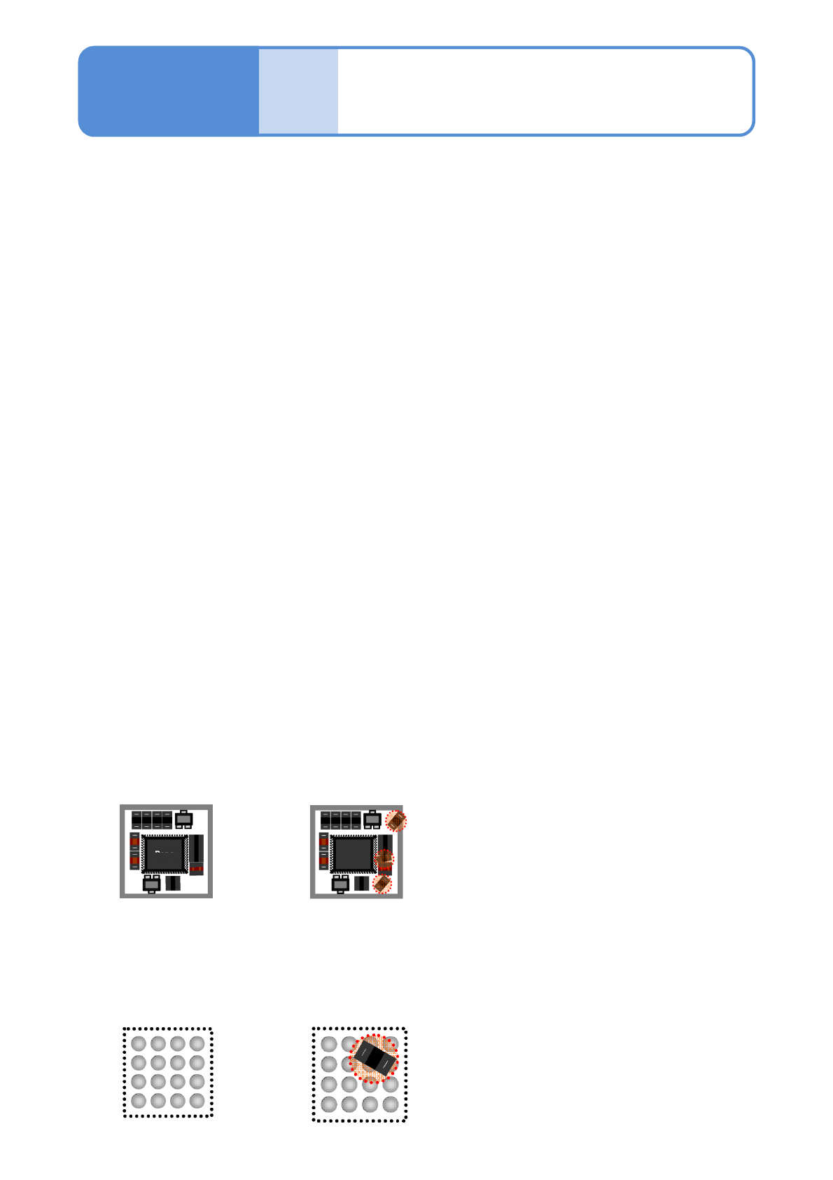
■Example of foreign body inspection of BGA components (*2)
Absence of foreign body
Presence of foreign body
Checks for the presence of foreign bodies (dust, scattering components, etc.) in a component placement area.
■Example of foreign body/under-case inspection of shield case components (*1)
Absence of foreign body Presence of foreign body
●Checks for the presence of any foreign bodies (dust, scattering components, etc.) in a placement area.
●Checks if all components in a component placement area are properly placed.
NPM-W2 EJM7DE-MB-04O-00
4-5-2-1
Component
inspection
Barcode scanner-
based operation 1
Operating procedure
4-5-2
Defec-
tive PCB
process
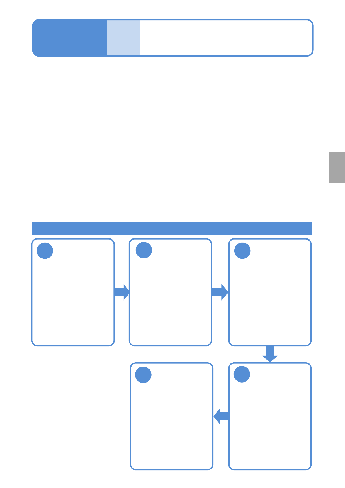
4
1
Remove a
defective PCB
Restart
transportation
5
3
Repair a defect
Reload the
repaired PCB
(→P.4-5-2-4)
2
Attach and read
a reload barcode
(→P.4-5-2-2)
●Turn ON the
transportation restart
switch (the foot switch,
etc.).
●Repair the defect,
monitoring it on the
optional display.
●The signal tower comes
on and the buzzer sounds.
●Reset with “NG eject
reset” on the inspection
monitor to reset.
(→P.4-4-3)
In order to control production data with the use of LNB, ID numbers are automatically assigned to all PCBs.
If production is resumed with PCBs left removed using the ejection conveyor, the production data of PCBs
controlled by LNB will differ from the actual number of PCBs produced. To avoid this, reload barcodes are
attached to removed PCBs and are linked with the ID numbers assigned to those removed PCBs.
●When a PCB is not to be reloaded, a barcode does not need to be attached to the PCB.
■Specifications for ejection conveyor
●PCBs judged as defective are suspended on the (inspection) ejection conveyor*1)*2).
●Press the transportation restart switch (such as the foot switch) connected to the (inspection) ejection
conveyor to restart transporting.
■Reload barcodes
*3)
●Reload barcodes are to be prepared by you.
●Be sure to attach a barcode and read the barcode data when removing a defective PCB, and also be
sure to read the barcode again before reloading the PCB.
*1) PCBs judged as conforming are not to be stopped on the inspection ejection conveyor.
*2) For more information on specifications for the ejection conveyor, see the NPM-W2 specification.
*3) For more information on specifications for reload barcodes, see the NPM-W2 specification.
Work flow of defective PCB process
●There are two types of
barcodes.
・PCB recognition
barcode
・Reload barcode