N7201A616E00_0317.pdf - 第318页
NPM-W 2 EJM7DE-MB-04 O-00 4-6 -1 A B C D E Oper a tion of the optional display f or NG map display Operating procedure 4-6 ● The optional d isplay and a cable sh ould be prepar ed on your ow n. ● It is connected to the M…
NPM-W2 EJM7DE-MB-04O-00
4-5-3
Component
inspection
Non-barcode scanner–
based operation
Operating procedure
4-5-3
Defec-
tive PCB
process
Only when such a communication switch as the one for bad mark recognition results is
turned OFF and inter-machine communication of information such as the one related to
bad mark recognition results is not needed, reloading operation can be performed without
having to use the barcode scanner.
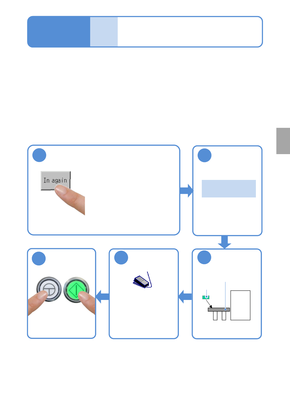
■Procedure for removing a defective PCB
Remove a PCB, which has been judged as defective, as is.
Repair the PCB in an appropriate manner, and store it temporarily so as to reload it.
1
●Unloading of PCBs on the
upstream side stops and the
machine comes to an immediate
(single) stop .
●When there is any PCB(s)
already loaded into the machine,
the machine comes to an
immediate stop after the PCB(s)
is unloaded from the machine.
3
Put the PCB on
the reload
conveyor
2
Confirm the
message
Reload conveyor
Repaired
PCB
『 Please put the
PCB.』
■Procedure for reloading a defective PCB
Operate as follows.
5
Start PCB
transportation
●Turn ON the
transportation restart
switch to start
transporting a PCB on
the reload conveyor.
Start production
ENABLING
START
4
NPM-W2 EJM7DE-MB-04O-00
4-6-1
A
B
C
D
E
Operation of the optional
display for NG map display
Operating procedure
4-6
●The optional display and a cable should be prepared on your own.
●It is connected to the MONITOR connector on the front of the inspection box.
([Maintenance] P.14-9)
Also the mouse is required. Please prepare it on your own.
●It is connected to the USB connector on the front of the inspection box.
([Maintenance] P.14-9)
●If the optional display for NG map display is placed on the inspection BOX, an operator may damage it by
hitting and knocking down with her/his body accidentally.
Secure the safety position such as beside the repair conveyor, and fix it not to fall.
●Never put anything, including the optional display for NG map display, on the inspection BOX.
Setting the soft switches
Turn ON the soft switch [Show NG map (monitor)] from [Setup of operation.]
(→P.4-2-1)
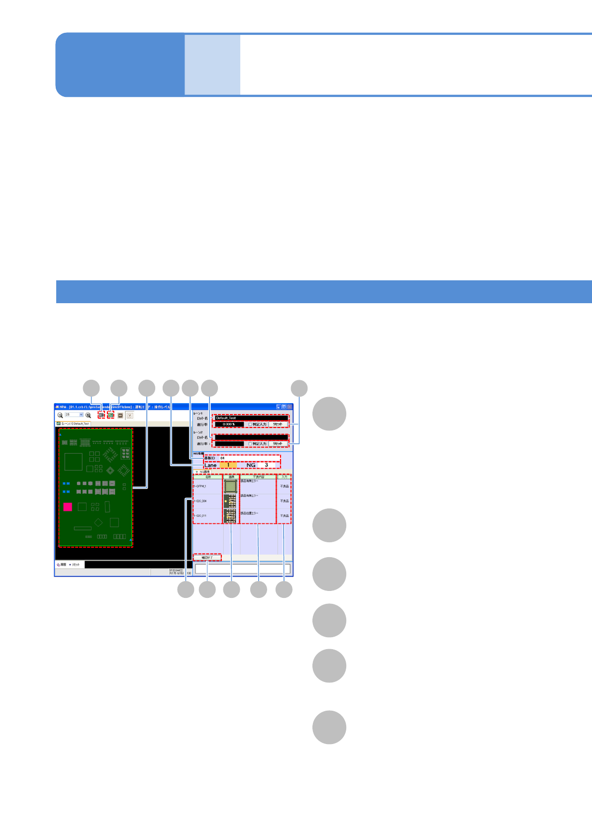
■Overall view of PCB
Lot name
NG map
PCB ID
Component name
NG image
A component is displayed in one of the
following colors, depending on the
inspection result.
●OK: Blue
●NG: Red
●Yet-to-be inspected: Gray
Displays NG image.
F
Defect
Displays an inspection item, regarding
which NG judgment has been formed.
D
H I BA
E F GJ
CK
L
NPM-W2 EJM7DE-MB-04O-00
4-6-2
G
Input
H
I
J
NG
undefinded
Overall view of PCB
Enlarged view of component’s
vicinity
Check end
(Exists to the NG screen for the next PCB)
Displays over judgment input results.
If judged to be defective
by the operator
If not yet judged by the
operator
Component
inspection
K
NG information
L
Judgment input
Lane : Lane number
NG : Number of NG components
The present first run rate is reset and starts over from the next PCB again.
Check ON : If over judgment input results in OK, the PCB is counted as OK PCB.
Check OFF : The result of over judgment input is not considered.