N7201A616E00_0317.pdf - 第329页
NPM-W 2 EJM7DE-MB-05O-0 0 5-3-1 -2 Solder inspection
NPM-W2 EJM7DE-MB-05O-00
Produc-
tion data
and
teach
5-3-1-1
Overview
Operating procedure
5-3-1
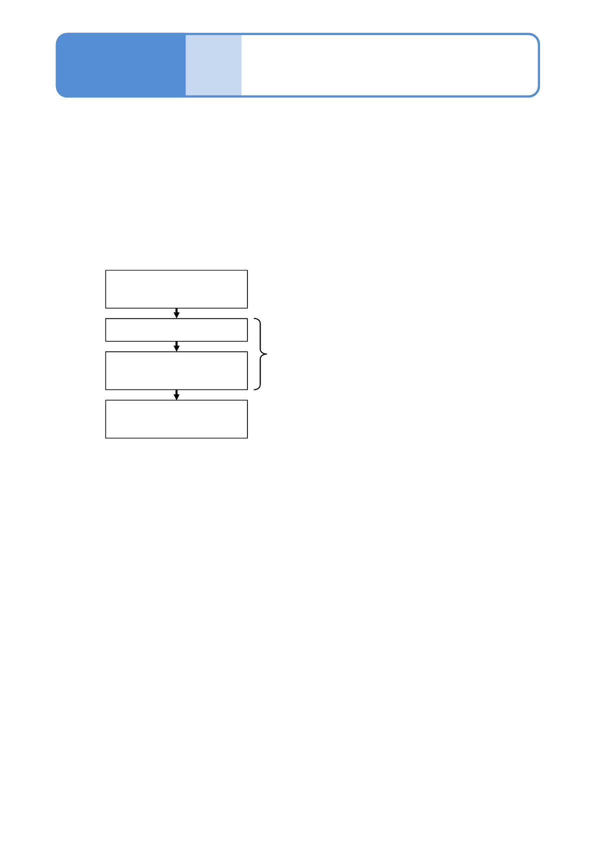
■Teaching flow
Creating the production data
(inspection FPV data)
Loading the production data
Capturing the images of the
teaching PCB
Setting with the 2D inspection
editor
Created by NPM-DGS
Edited with NPM-DGS
Operated by the machine
This section describes teaching that is intended to conduct solder inspection.
For the purpose of judging whether solder is on board or not, teaching of solder colors is conducted on NPM-
DGS. The teaching of solder colors is judged by taking the images of solder on board using the inspection
head.
[2D inspection editor] of the NPM-DGS is used to edit production data after inspection.
●NPM-W2 system equipped with the inspection head can configure only the [Setting of soft switches].
The mouse, keyboard, or monitor connected to the system unit of NPM-W2 or the inspection BOX cannot
be used to edit production data.

NPM-W2 EJM7DE-MB-05O-00
5-3-1-2
Solder
inspection
NPM-W2 EJM7DE-MB-05O-00
5-3-2-1
Capturing the images
of teaching PCB 1
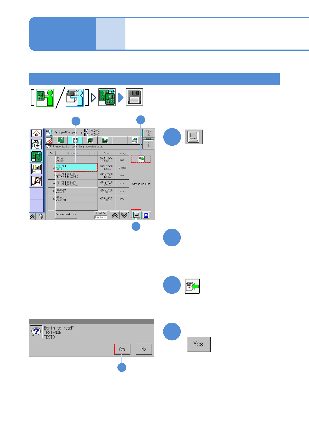
Loading the production data
1
Operating procedure
5-3-2
●The target device is switched to LNB.
(The filename of the data registered in
an LNB list is displayed.)
Choose the desired filename
(The selected filename is displayed in
light blue.)
●Pressing [Date] sorts the filename in
descending order of date.
2
3
4
Produc-
tion data
and
teach
Confirm the message
3
2
4
1
(The data starts downloading)
This section describes how to capture an image of a PCB having soldered components, which is used for
data edit on “2D inspection editor”.