N7201A616E00_0317.pdf - 第361页
NPM-W 2 EJM7DE-MB-06O-0 0 6-1-1 -2 Setting change
NPM-W2 EJM7DE-MB-06O-00
Data
editing
6-1-1-1
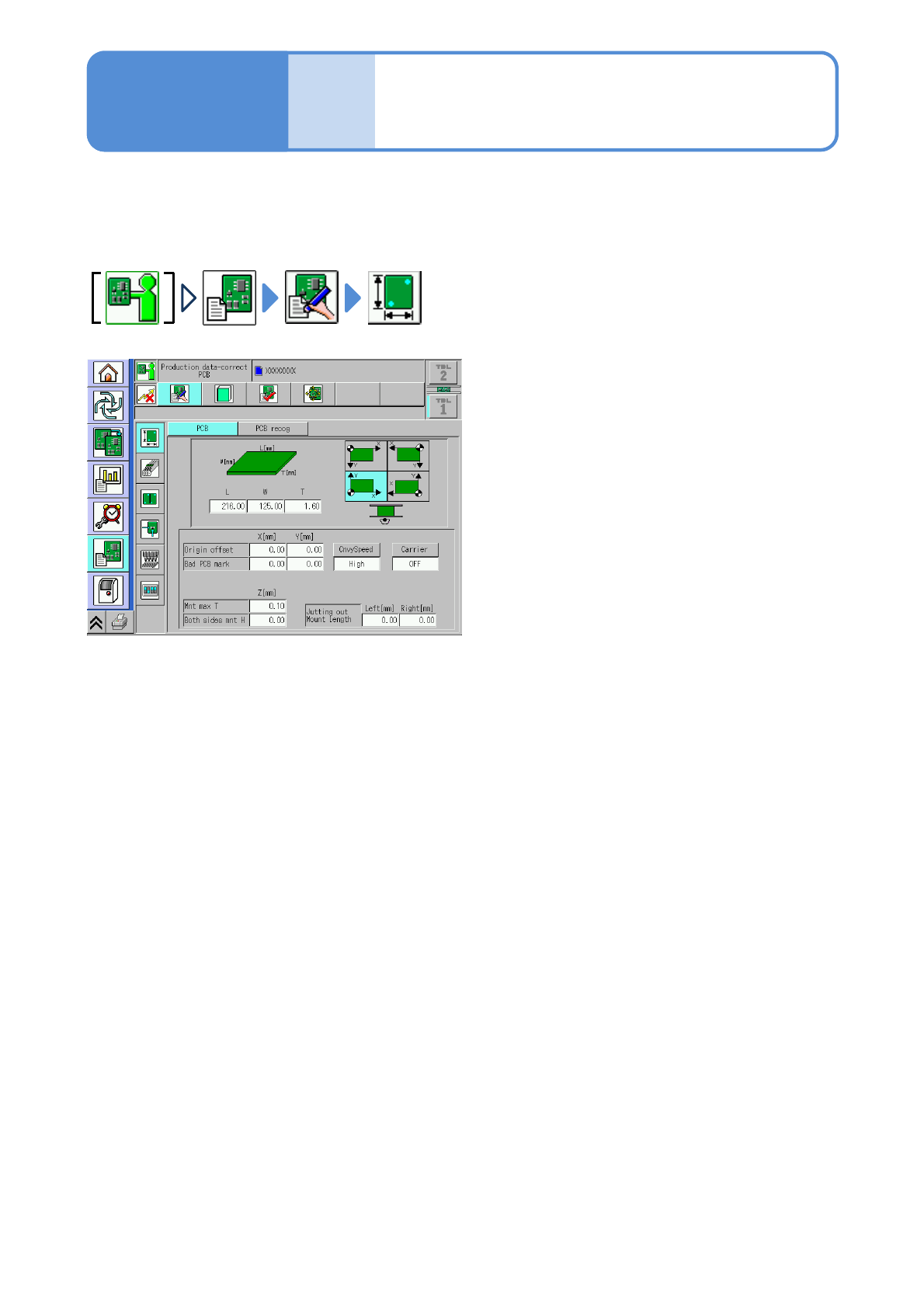
You can check or modify the data related to production.
●Parameter details in: (→ Chapter 5 ‘PCB EDIT’ in [NPM-DGS] Operating Instructions)
If the data is modified while LNB is connected, it is automatically uploaded to LNB.
Overview of data edit
Operating procedure
6-1-1

NPM-W2 EJM7DE-MB-06O-00
6-1-1-2
Setting
change
NPM-W2 EJM7DE-MB-06O-00
Data
editing
6-1-2-1
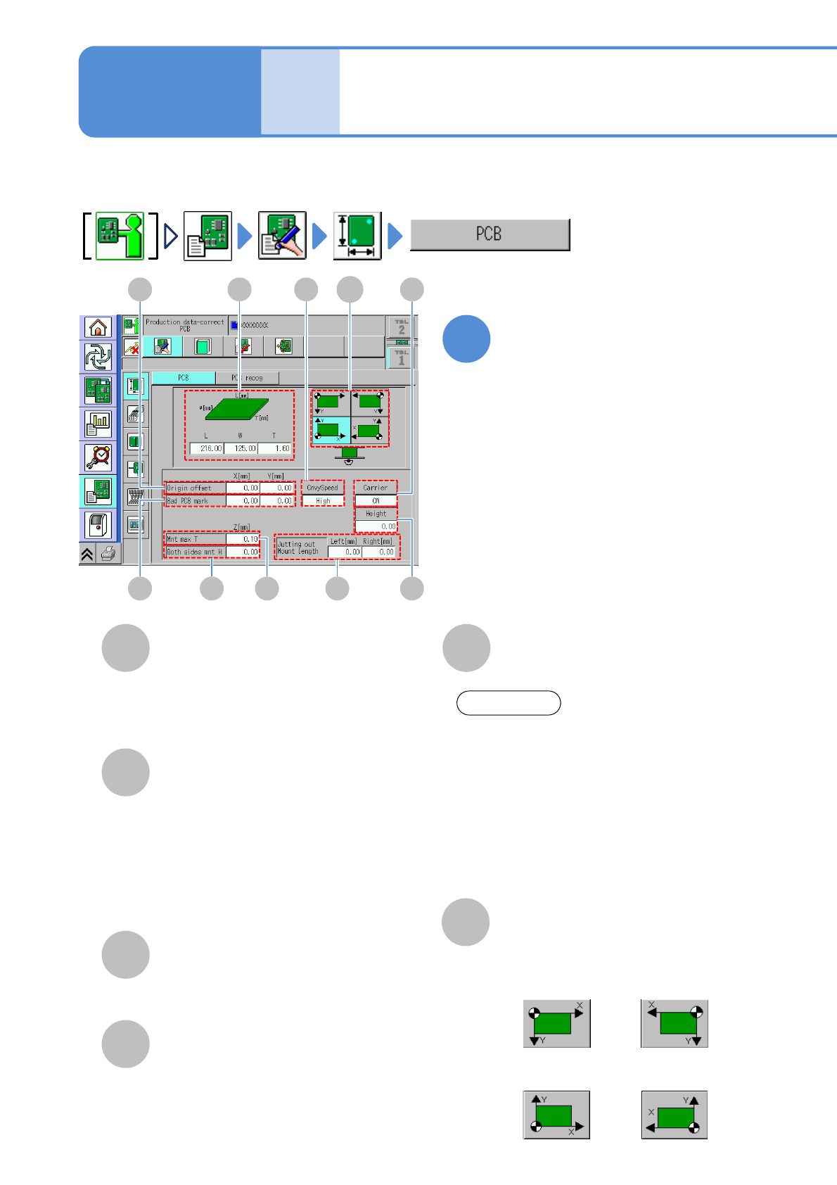
A
Origin offset
D
B
C
The maximum height of the components
that are already placed on the front side.
Both sides mnt H
Bad PCB mark
Edit the data by pointing the
cursor to the desired field
●Touching the screen opens the input
window.
Enter all the offset values of origin for
placement coordinates, PCB recognition
coordinates and bad mark coordinates.
Coordinates of bad mark.
●If the coordinates have this mark, it is
regarded as defective, where
placement will not be carried out.
●To edit it, set [ON] of [Detect Bad
Board Mark] of the soft switch.
(→P.6-1-20)
The maximum height of the components
that are already placed on the rear side.
Mnt max T
1
PCB data edit
Explains how to check and modify the PCB data.
E
PCB dimensions
Enter PCB dimensions.
Operating procedure
6-1-2
D C
A
B
G HE
J
F
I
●Right-front
reference
●Left-front
reference
●Right-rear
reference
●Left-rear
reference
F
Coordinate standard
Choose the PCB coordinate reference.
ATTENTION
Regarding PCB width, you may be able to
input a little bit larger value than the
maximum size of the machine PCB
specifications. It means that the
maximum width can be input on the
machine mechanism because we give
you extra space for variation of your PCB
size. However, regarding a PCB
exceeding the maximum size of PCB
specifications, we do not guarantee.