N7201A616E00_0317.pdf - 第390页
NPM-W 2 EJM7DE-MB-06O-0 0 Data editing 6-1-10 -1 Describes how to check and edit tray information. B C D E F G T r ay data edit (tray feeder) A H A CompName ( → P.6-1-6) B Tr a y Tray name. C Basic information ( → P.6-1-…
NPM-W2 EJM7DE-MB-06O-00
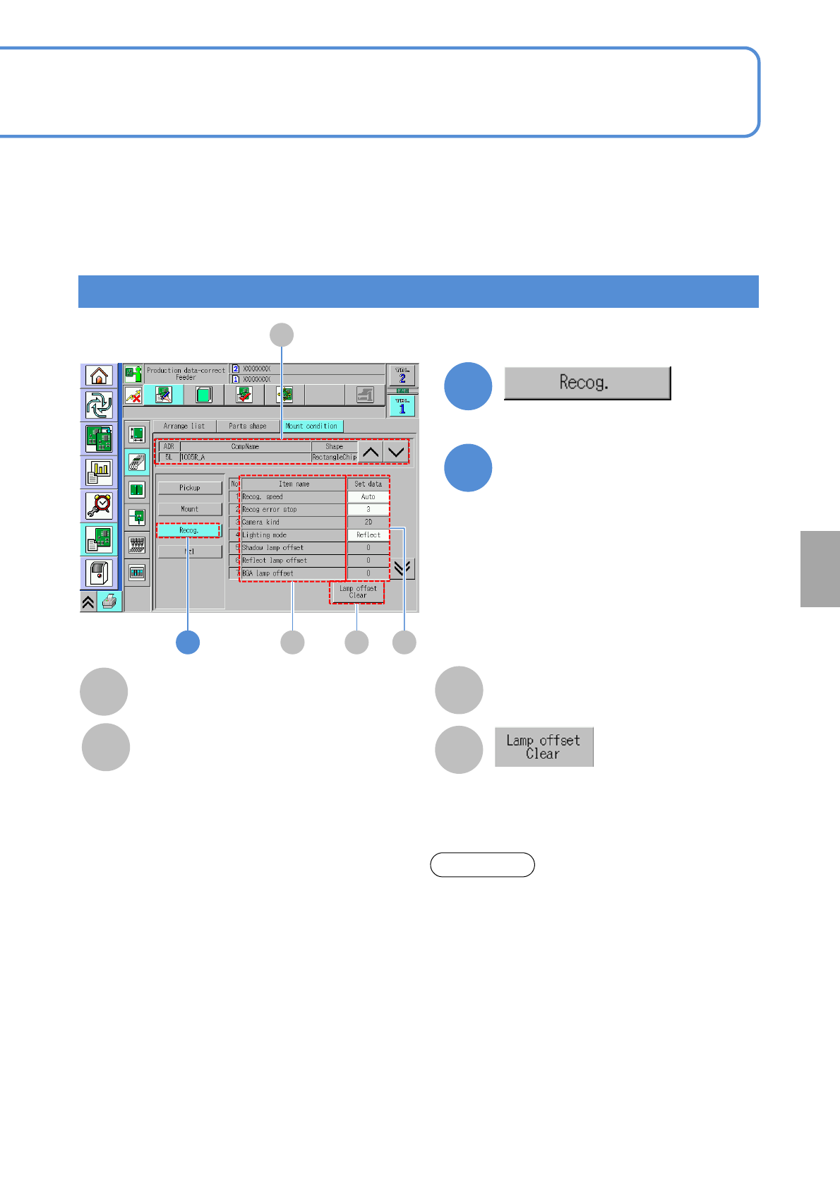
The offset data of lamp value is
initialized.
1
1
Checking and editing the recognition condition
6-1-9-2
B CD
C
B
Item name
Set data
Placement condition of each item.
D
A
A
CompName
(→P.6-1-8)
Edit the data of the desired
field on the screen
●Touching the screen opens the input
window.
2
Setting
change
Recog. Speed:
・(Auto / Fast / Mid / Slow)
Recog error stop:
・(1 / 3)
Camera kind:
・(2D / 3D / 3D(Multi))
Lighting mode:
・(Shadow / Reflect / BGA)
Shadow lamp offset:
・Shadow lamp offset value for component
recognition
Reflect lamp offset:
・Reflect lamp offset value for component recognition
BGA lamp offset:
・BGA lamp offset for component recognition
polarity:
・The presence / absence of component polarity
Chk adhesion around the parts:
・Picking up 2 components results in a recognition
error. Prevents an extra component from falling on a
PCB.
About the light setting of the multi-recognition
camera [Type 3].
1. When the reflecting light is illuminated, the BGA
ball height inspection is not performed.
2. The BGA lamp value is automatically converted
inside the system. Therefore, when the BGA ball
height inspection is performed, the different
value from the one set on the recognition screen
may be displayed.
3.To keep the 3D inspection condition, sometimes
the recognition system automatically changes
the lamp value.
ATTENTION
NPM-W2 EJM7DE-MB-06O-00
Data
editing
6-1-10-1
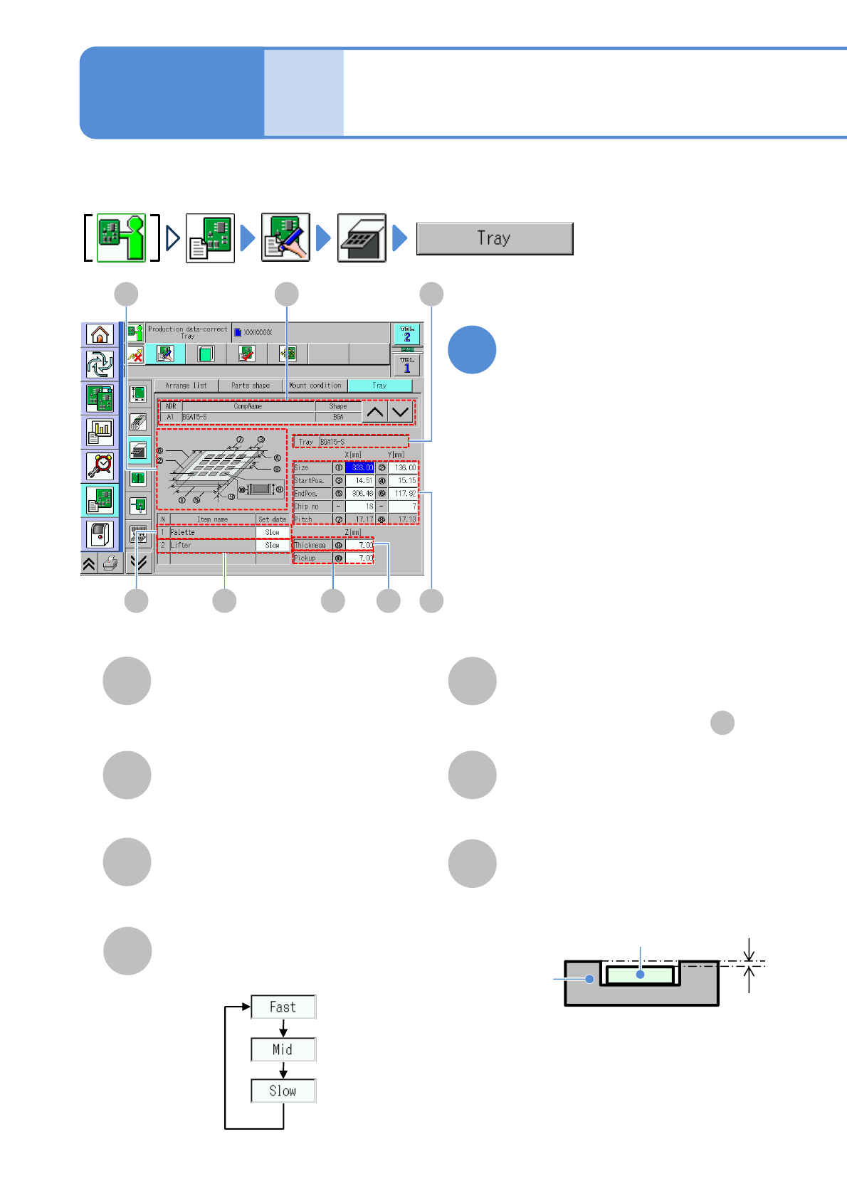
Describes how to check and edit tray information.
B
CD E F G
Tray data edit
(tray feeder)
AH
A
CompName
(→P.6-1-6)
B
Tray
Tray name.
C
Basic information
(→P.6-1-6)
Choose a moving speed of pallet axis.
D
Pallet axis speed
E
Lifter axis speed
Choose a moving speed of lifter-axis.
●Choose the same set data as .
D
F
Tray thickness
G
Pickup height
Tray
Electric
component
Pickup
height
Enter the pickup height.
Edit the data of the desired
field on the screen
●Touching the screen opens the input
window.
1
Operating procedure
6-1-10
NPM-W2 EJM7DE-MB-06O-00
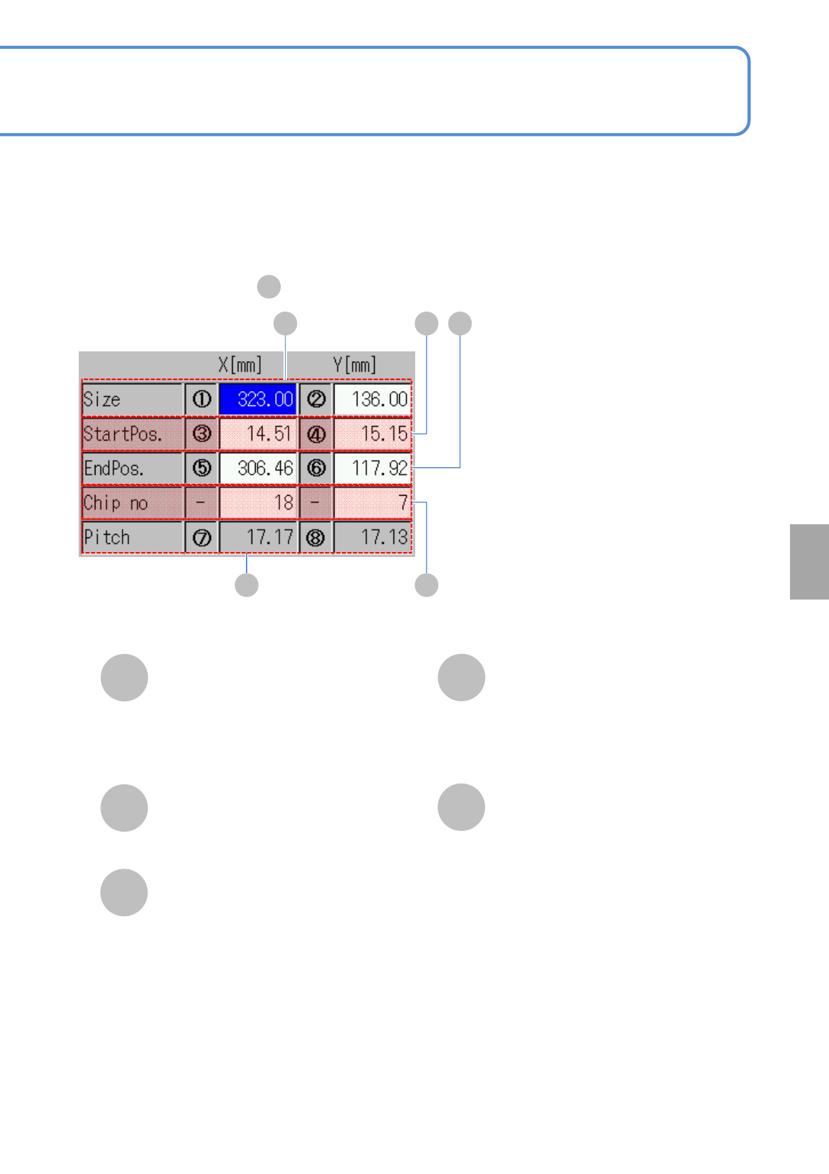
Size
H
StartPos.
Chip no
Pitch
6-1-10-2
■Enlarged drawing of
C
KL
H I J
Enter the outer dimensions of a tray.
X: Dimension of longer side.
Y: Dimension of shorter side.
I
Enter the first pickup point coordinates.
J
EndPos.
Enter the last pickup point coordinates.
K
X: The number of components stored in
the longer side.
Y: The number of components stored in
the shorter side.
●Unit: piece.
L
Pitch between components.
Setting
change