N7201A616E00_0317.pdf - 第419页
NPM-W 2 EJM7DE-MB-06O-0 0 6-1-18 -6 Setting change
NPM-W2 EJM7DE-MB-06O-00
6-1-18-5
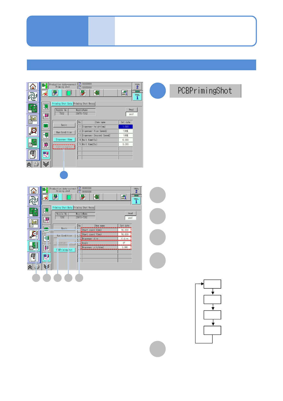
Setting PCB dummy dispensing
Only when the dummy dispensing pattern is [PCB])
A
A
Start coord X (mm)
The start X coordinate of dummy
dispensing is displayed.
1
1
B C D E
B
Start coord Y (mm)
The start Y coordinate of dummy
dispensing is displayed.
C
Dispenser dire
The direction of dummy dispensing on a
PCB is displayed
D
Dispenser angle
E
Dispenser pitch (mm)
Data
editing
Operating procedure
6-1-18
Dummy dispensing
data edit 3 (dispensing head)
0°
90°
180°
270°
Choose the angle of a dispensing head
as the stopper does not contact to the
electrode.
●You are allowed to enter the value
when [PCB] is selected on [Dummy
dispensing pattern].

NPM-W2 EJM7DE-MB-06O-00
6-1-18-6
Setting
change

NPM-W2 EJM7DE-MB-06O-00
F
6-1-19-1
B
A
You can view and set various recognition data used in dummy dispensing recognition
The applicable nozzle position is
displayed.
B
Nozzle No
C
NozzleName
D
Lighting
Brightness of the head camera lighting is
displayed.
Coax:
The lamp value of the coaxial is displayed.
H-angle:
The lamp value at the high angle is
displayed.
M-angle
The lamp value at the middle angle is
displayed.
L-angle
The lamp value at the low angle is
displayed.
E
Search area (mm)
Begin X:
The X coordinate at the lower left of the
search area is displayed.
Begin Y:
The Y coordinate at the lower left of the
search area is displayed.
End X:
The X coordinate at the upper right of
the search area is displayed.
End Y:
The Y coordinate at the upper right of
the search area is displayed.
ACD
G
E
H
Data
editing
Operating procedure
6-1-19
Dummy dispensing
recognition data edit
(dispensing head)