N7201A616E00_0317.pdf - 第451页
NPM-W 2 EJM7DE-MB-06O-0 0 6-2-3 -8 Setting change 11 13 14 12 11 + (Measur e all mea surement coo rdinates and the result is displayed.) Confirm the PCB exists and the message 12 + 13 Difference: T he difference b etween…
NPM-W2 EJM7DE-MB-06O-00
6-2-3-5
Produc-
tion data
teaching
PCB warpage measurement
point teach 3
(option)
Operating procedure
6-2-3
Teaching procedure 2
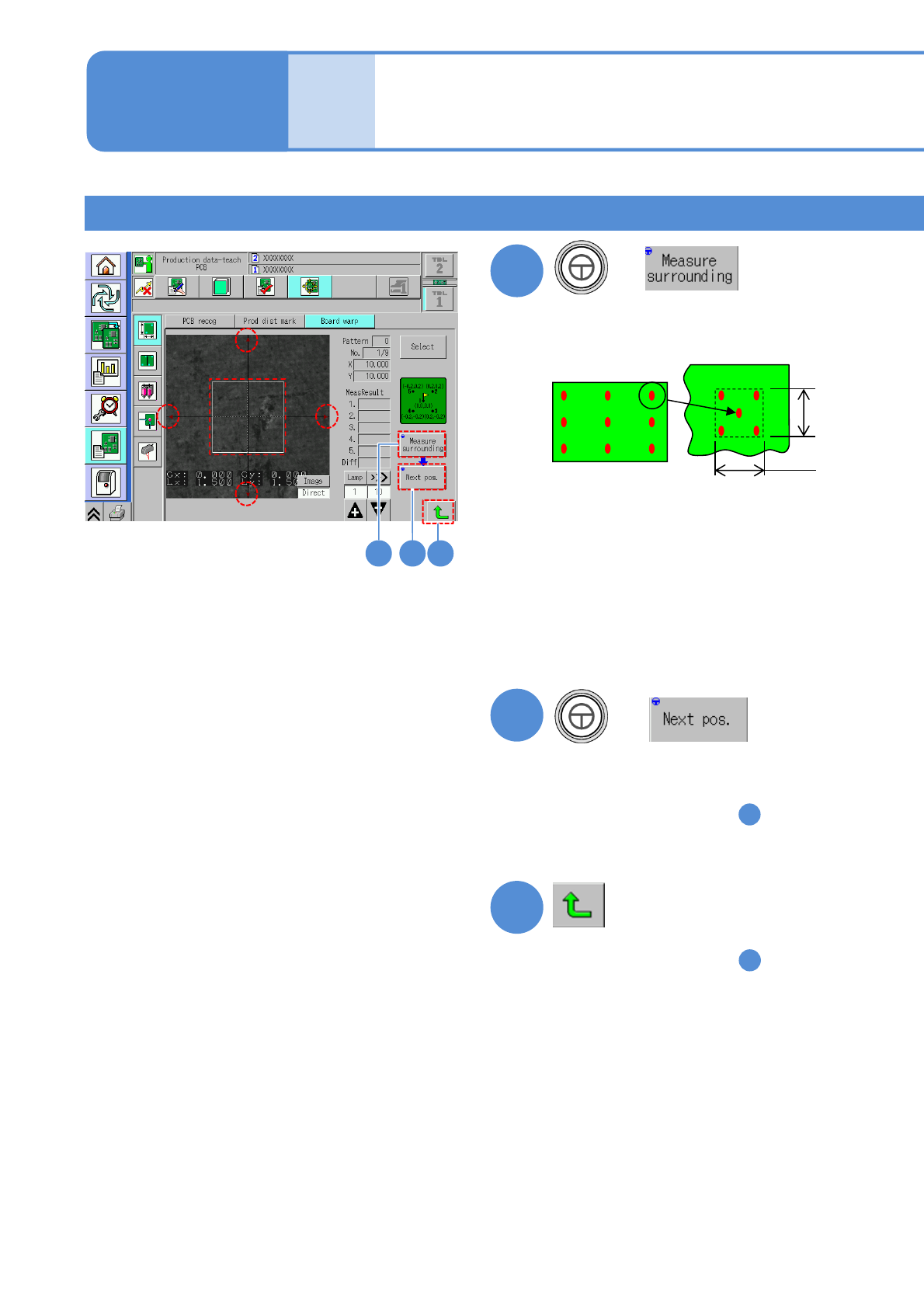
8 9 10
+
(Measure the selected measurement
coordinates and four points around it,
and the result is displayed.)
8
9
(Move to the next measurement point)
●Confirm the following point
1
2
3
4
5
1.5 mm
1.5 mm
The difference between the
measurement point (center) and its
surrounding is 0.03 mm or less
●If the measurement result is unstable
Adjust to be applicable position with
inching, and measure surroundings
again.
(Adjust as a boundary of a copper foil
is not included within □1.5 mm)
+
●Confirm all points
●If you change the measurement
coordinates in the step , you are
asked whether or not to save the
changed coordinates.
Select either one.
8
10
●If you change the measurement
coordinates in the step , you are
asked whether or not to save the
changed coordinates.
Select either one.
8
NPM-W2 EJM7DE-MB-06O-00
6-2-3-8
Setting
change
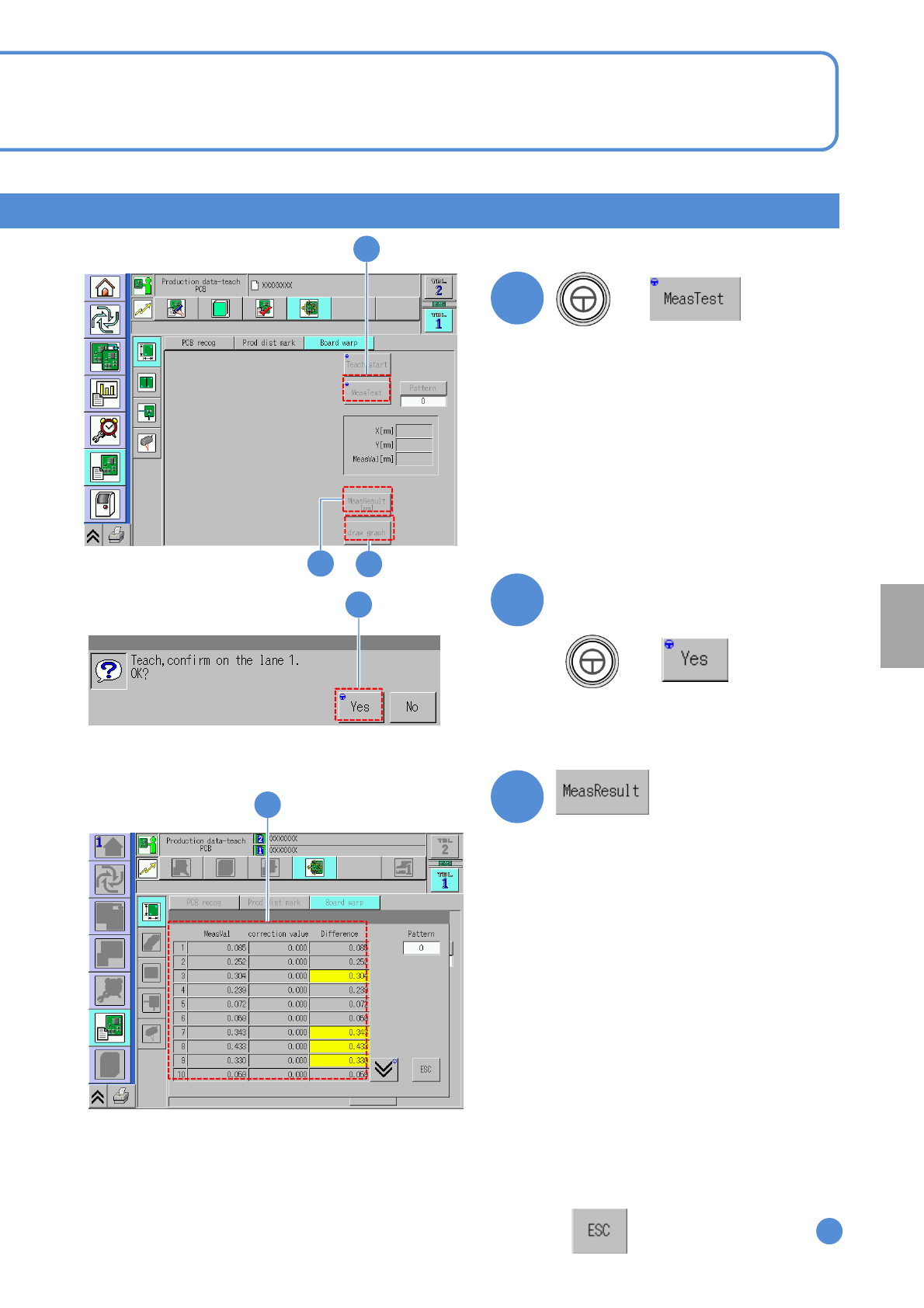
11
13
14
12
11
+
(Measure all measurement coordinates
and the result is displayed.)
Confirm the PCB exists and the
message
12
+
13
Difference: The difference between
measured value and correction value
13
Measured value: The difference between the
perfect PCB top surface and the measured
PCB top surface
(If the measured PCB top surface is
higher
than perfect one, it displayed as positive
value)
Correction value: The same coordinate value
of the correction curve calculated from
the measurement result
●If the difference exceeds 0.3 mm, it
results in error, the background in the
frame turns in yellow.
For obtaining the applicable correction
curve, review the measurement
points. Also, if the measured value or
correction value is -4.5 mm or less,
or +2 mm or over,, it results in error.
:Transitions to the screen
11
NPM-W2 EJM7DE-MB-06O-00
6-2-3-7
Produc-
tion data
teaching
PCB warpage measurement
point teach 4
(option)
Operating procedure
6-2-3
Teaching procedure 3
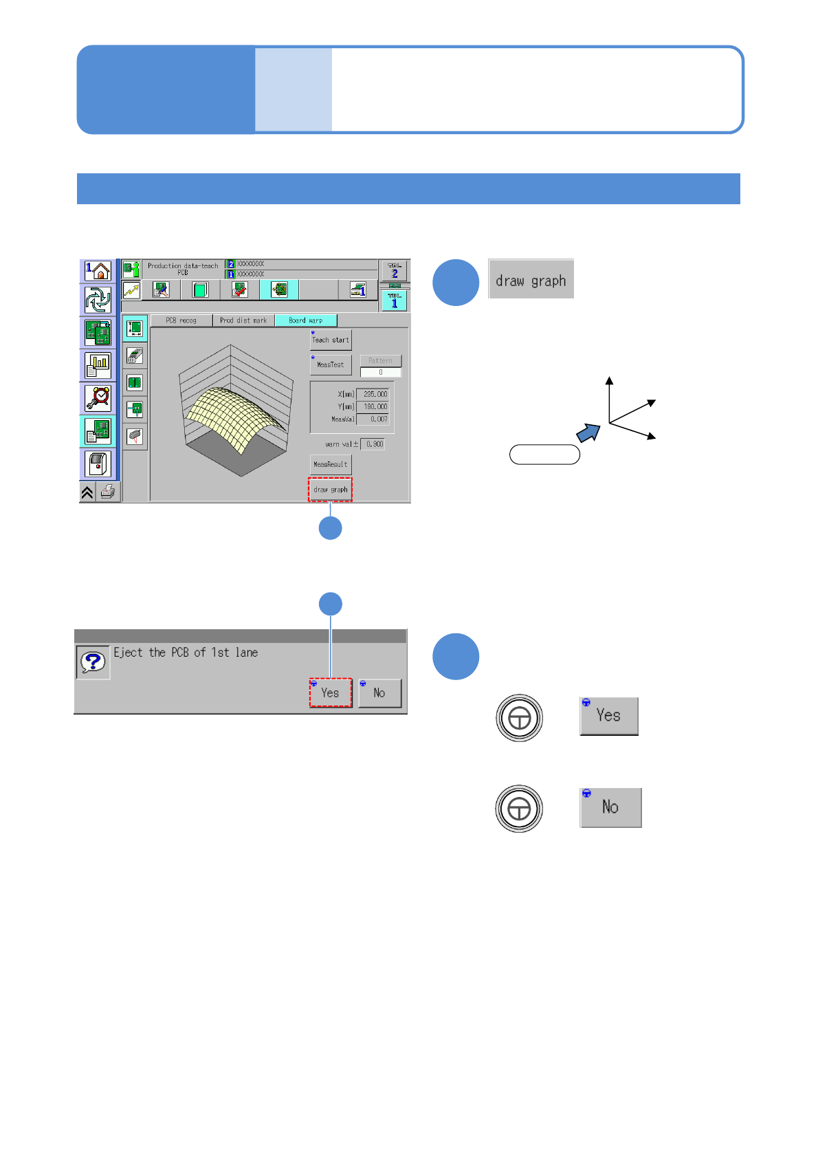
14
Displays the PCB warpage condition
15
Press any other menu button and
confirm the message
+
15
●Displays only when LNB is connected.
Z
Y
X
Front
The graph is as seen from the front
14
■When you do not unload the PCB
+