N7201A616E00_0317.pdf - 第488页
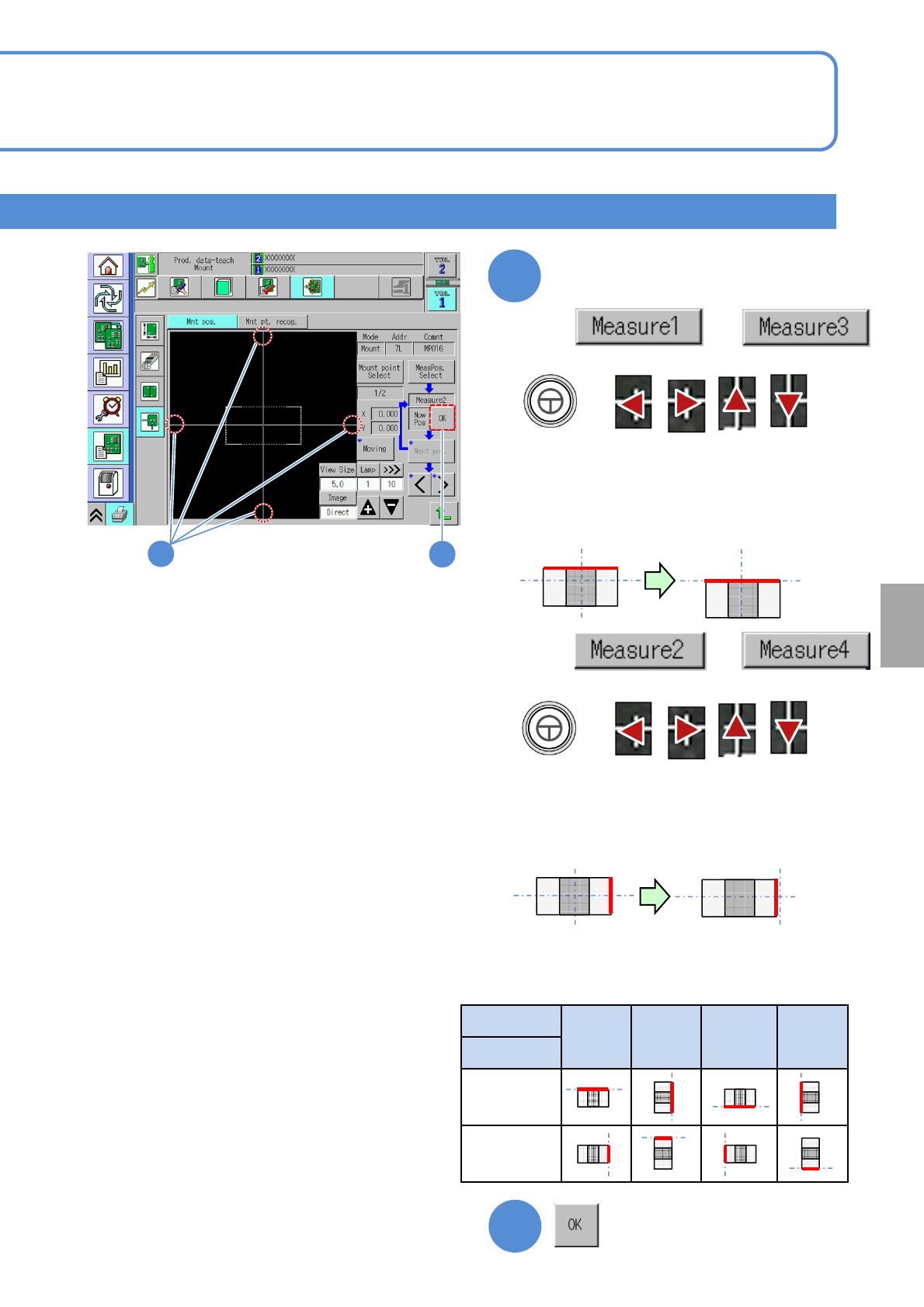
NPM-W 2 EJM7DE-MB-06 O-00 6-2-9 -11 Produc- tion data teaching Placement coor dinates teac h 6 Operating procedure 6-2-9 7 + ● Align the cross line to the top of the component electrode. Align the cross line to an electr…
NPM-W2 EJM7DE-MB-06O-00
6-2-9-10
Setting
change
5
+
●Align the cross line to the top of the
component.
Align the cross line to the edge
of a component
●The edge face of the component to align the
cross line differs depending on component
placement angle. (See below)
6
+
●Align the cross line to the right side of the
component.
●The edge face of the component to align the
cross line differs depending on component
placement angle. (See below)
Angle
0° 90° 180° -90°
Position
Measure 1
Measure 3
Measure 2
Measure 4
■Component edge face to align the cross line
6
5
are selected
■
are selected
When and
■
When and
●Notice1 (→P.6-2-9-7)
NPM-W2 EJM7DE-MB-06O-00
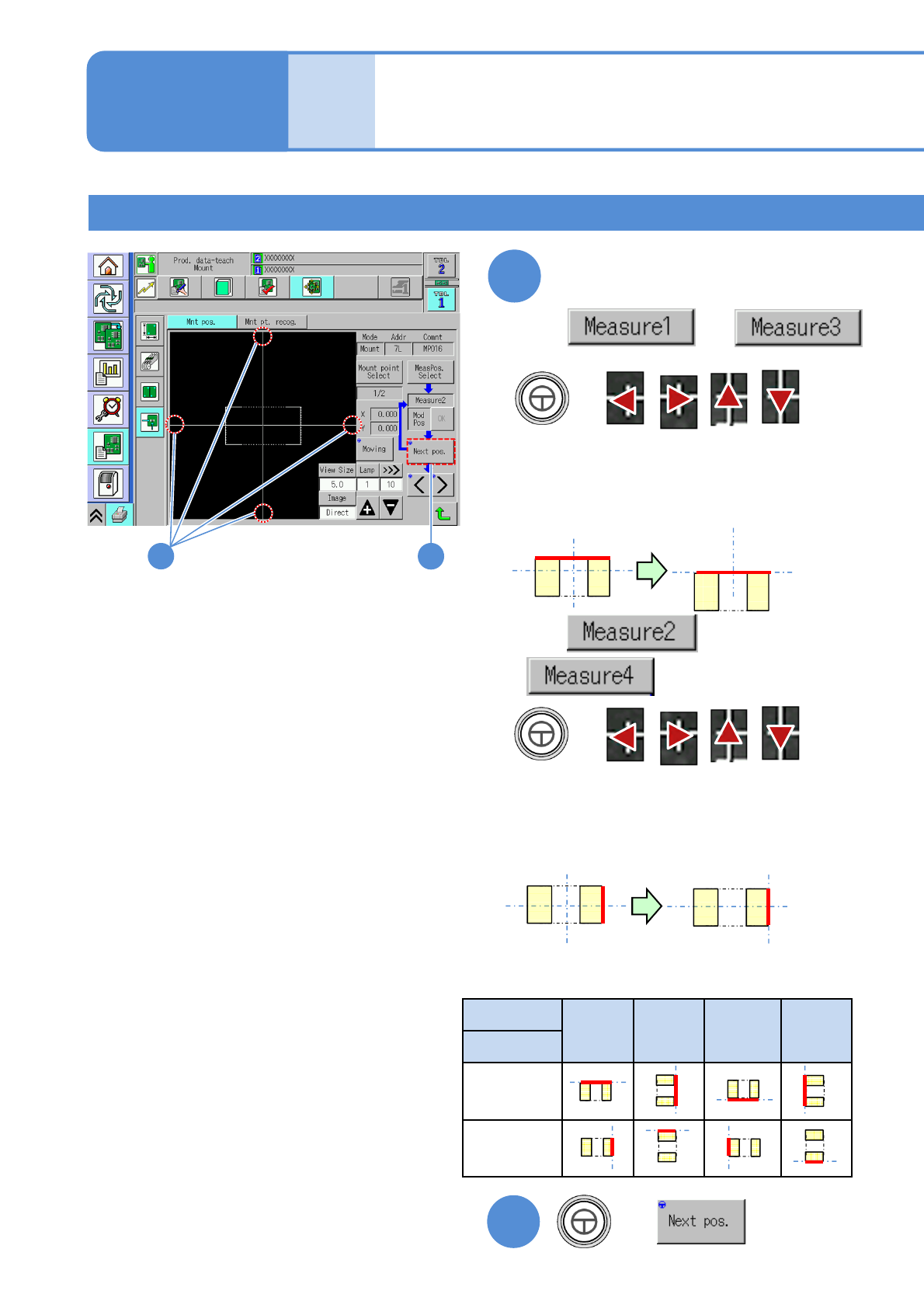
6-2-9-11
Produc-
tion data
teaching
Placement coordinates
teach 6
Operating procedure
6-2-9
7
+
●Align the cross line to the top of the component
electrode.
Align the cross line to an
electrode on the PCB
●The edge face of the component to align the
cross line differs depending on regular
component placement angle. (See below)
8
+
●Align the cross line to the right of the
component electrode.
●The edge face of the component to align the
cross line differs depending on regular
component placement angle. (See below)
Angle
0° 90° 180° -90°
Position
Measure 1
Measure 3
Measure 2
Measure 4
■Electrode position on a PCB align the cross line
+
8
7
are selected
■
are selected
When and
■
When and
Teaching with component (measuring method: 2 point) 2
●Notice1 (→P.6-2-9-7)
NPM-W2 EJM7DE-MB-06O-00
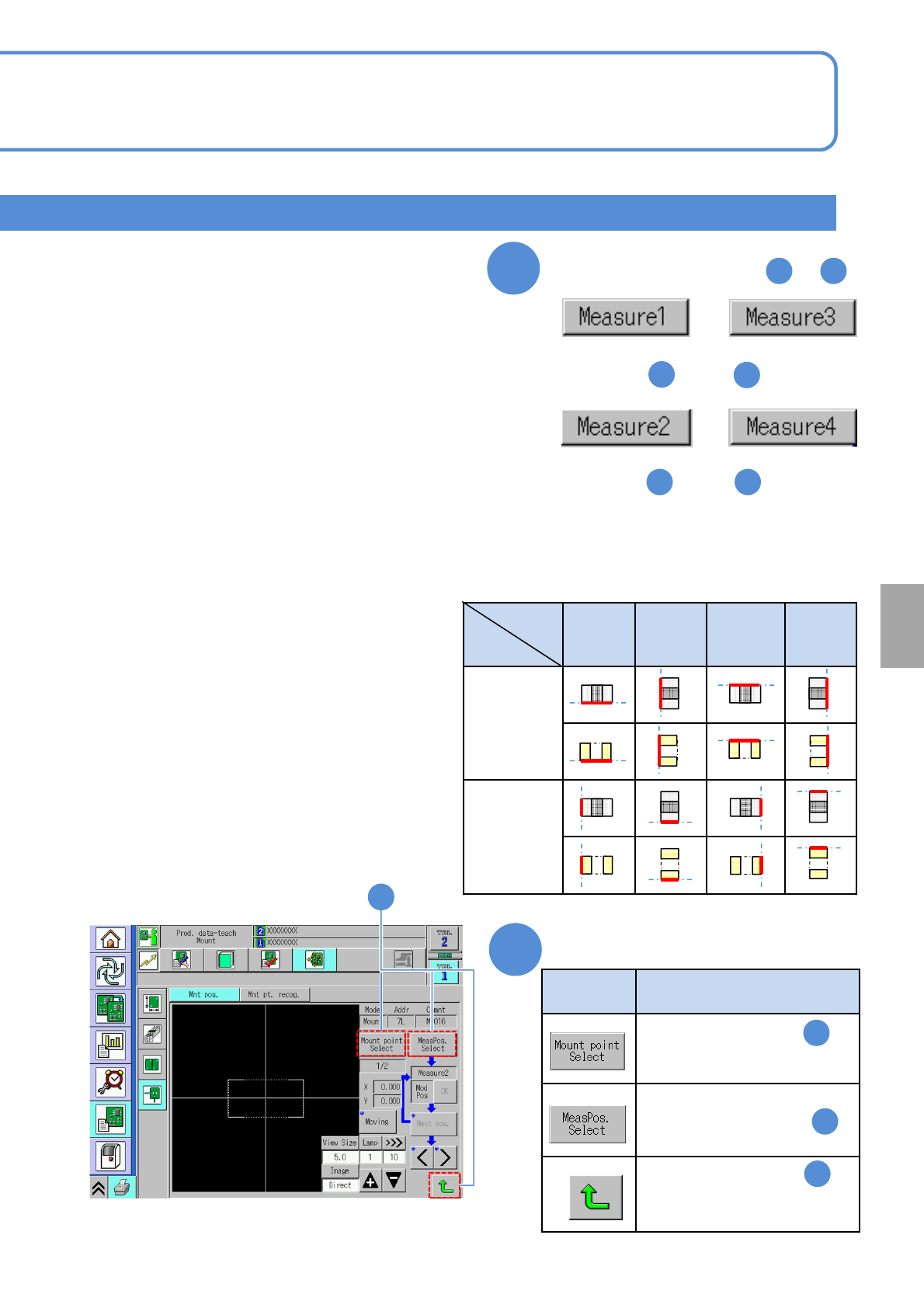
6-2-9-12
Setting
change
Type Action
Return to the screen in of
[Teaching with component
(measuring method: 1 point)]
Repeat once steps from to
2 8
9
Perform steps from through ,
changing from [Top] to [Bottom].
5
7
Perform steps from through ,
changing from [Right] to [Left].
5 7
●The edge face of the component to align the cross
line differs depending on placement angle. (See
below)
10
Press any of the following buttons
1
5
2
Return to the screen in
Return to the screen in of
[Teaching with component
(measuring method: 1 point)]
10
are selected
■
are selected
When and
■
When and
0° 90° 180° -90°
Measure 1
Measure 3
Measure 2
Measure 4
■The edge face position to align the cross line
Angle
Position