N7201A616E00_0317.pdf - 第612页
NPM-W 2 EJM7DE-MB-07 O-00 Display area of is displayed in light blue color. The front/rear/right/left of the display areas of and are displayed. You can ch eck the plac ement surface offs et (calibr ation result) used in…
NPM-W2 EJM7DE-MB-07O-00
7-3-2
Machine
parame-
ter
Placement position
offset check
Operating procedure
7-3-2
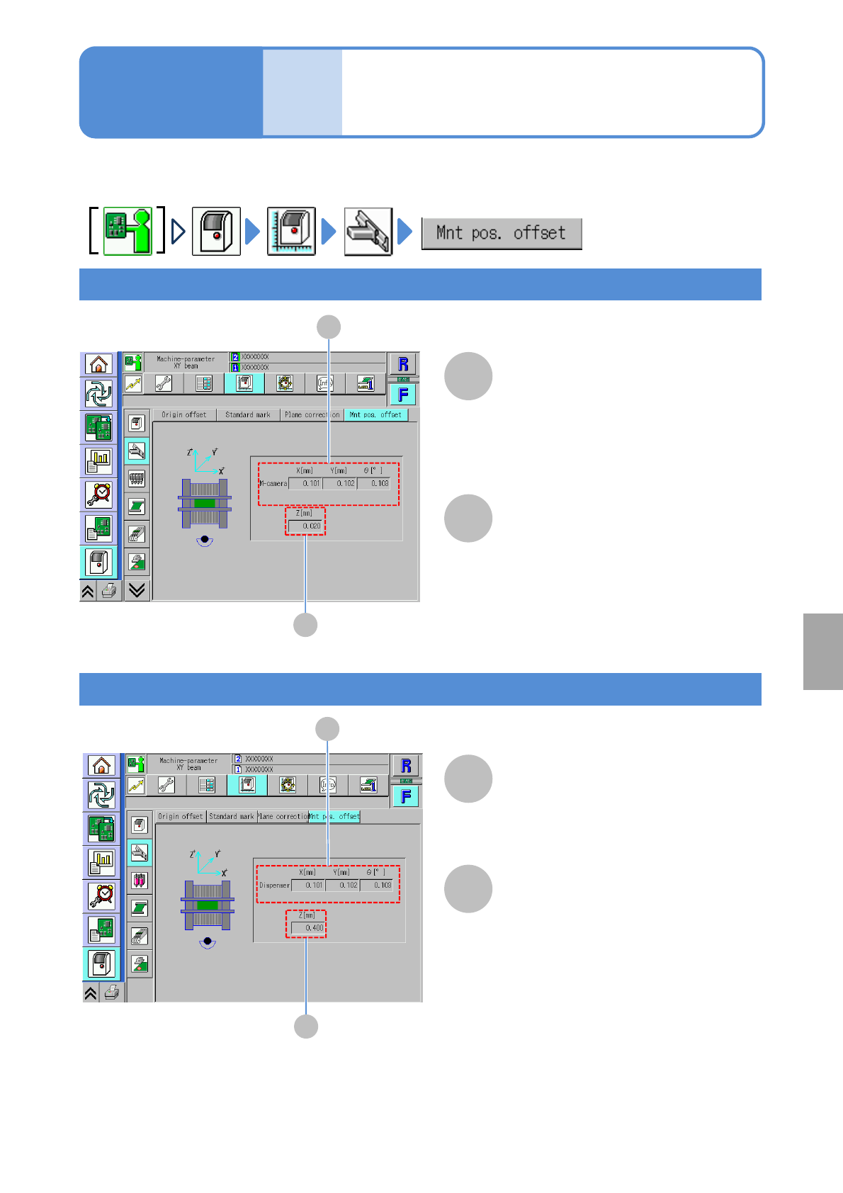
You can check placement position offset.
Multi-recognition camera
X[mm]/Y[mm]/ θ[°]
Displays X-, Y- and θ-coordinates
corresponding to the multi-recognition
camera on the placement position offset.
A
B
B
A
Z [mm]
Displays Z-coordinate on the
placement position offset.
Placement head
A
B
B
A
Dispensing head
Dispensing
X[mm]/Y[mm]/ θ[°]
Displays X-, Y- and θ-coordinates
corresponding to the placement position
offset (dispensing).
Z [mm]
Displays the Z-coordinate on the
placement position offset (dispensing).
System
administration
NPM-W2 EJM7DE-MB-07O-00
Display area of is displayed in light
blue color.
The front/rear/right/left of the display
areas of and are displayed.
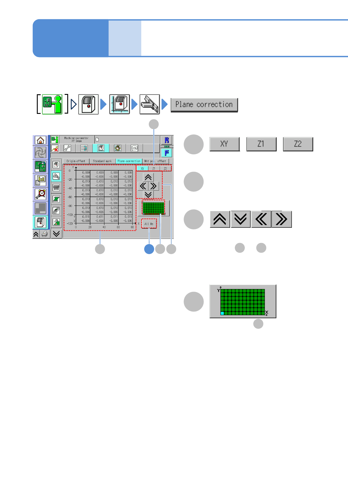
You can check the placement surface offset (calibration result) used in correcting PCB recognition and
placement positions.
7-3-3-1
Machine
parame-
ter
XY/Z plane correction
check
A
C
C
B
A
B 4
//
D
B D
B
Operating procedure
7-3-3
Switches between offset displays.
Offset
Placement surface offset.
●Displayed at intervals of 20 mm.
D
NPM-W2 EJM7DE-MB-07O-00
31
1
3
7-3-3-2
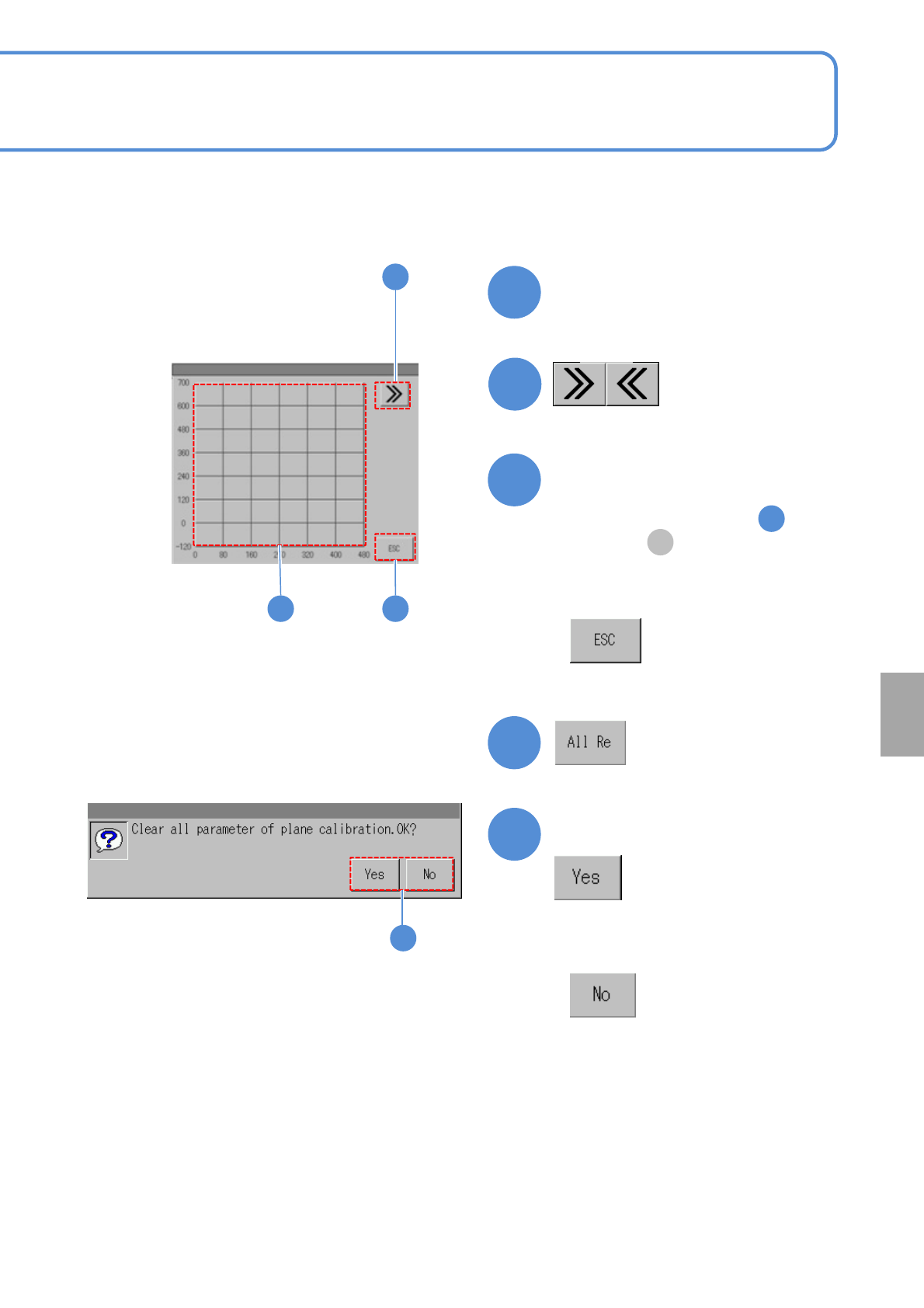
■To change the offset display area using a matrix
2
4
5
B
3
2
5
Touch the display area
(Matrix moves right or left)
(Offset of the area selected in is
displayed in )
■When you do not select the area to
display the offset
Choose an area to display the
offset
■When you do not clear plane
correction parameters
Confirm the message
System
administration