N7201A616E00_0317.pdf - 第627页
NPM-W 2 EJM7DE-MB-07 O-00 Machine parame- ter Operating procedure 7-3-15 Con v ey or origin of fset ch e ck A Checking origin offset You can check conveyor origin offse t (calibration result). ● For dual lane mode, you n…
NPM-W2 EJM7DE-MB-07O-00
Machine
parame-
ter
Operating procedure
7-3-14
7-3-14
A
C
B
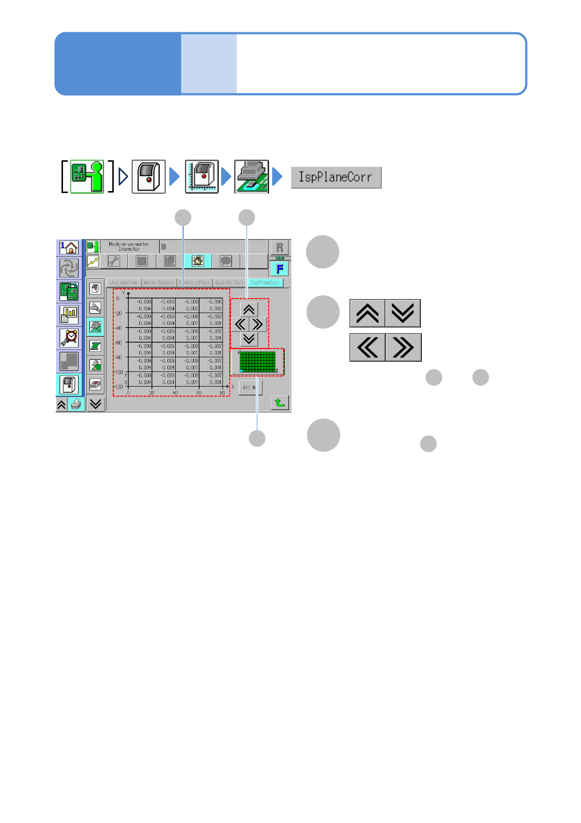
Inspection plane offset
check (inspection head)
You can check the offset value (calibration result) of the bonding side used when the inspection head
corrects the PCB recognition position and placement position.
A
Offset
Offset values of the bonding side
●Displays every 20 mm interval.
B
C
:Vertical direction
:Horizontal direction
●Displays area and .
A C
Area display
●Displays area in blue color.
A
NPM-W2 EJM7DE-MB-07O-00
Machine
parame-
ter
Operating procedure
7-3-15
Conveyor origin offset
check
A
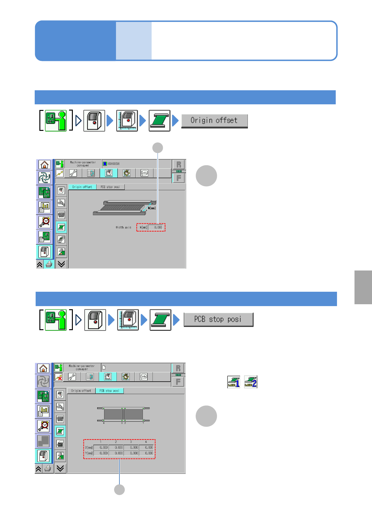
Checking origin offset
You can check conveyor origin offset (calibration result).
●For dual lane mode, you need to choose a lane in advance.
Width axis
Conveyor width offset.
7-3-15
A
System
administration
Checking PCB stop position offset
A
A
PCB stop position offset
X[mm]/Y[mm]
■For dual conveyor
(Select a lane in advance)
NPM-W2 EJM7DE-MB-07O-00
Machine
parame-
ter
Head camera offset
check
設備に設置されているフィーダーのメモリー情報を表示します。
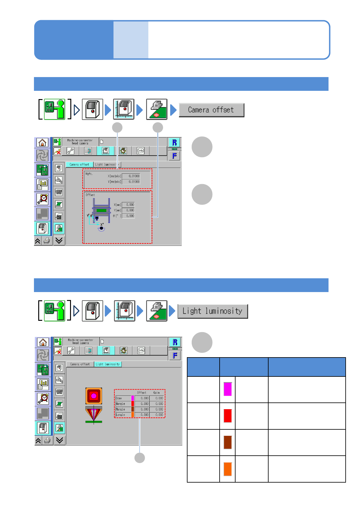
Checking magnification and offset
Checking light luminosity
A
A
A
B
B
Operating procedure
7-3-16
Mgfc. X[mm/pix]/Y[mm/pix]
Magnification of the head camera set to
the recognition device.
●Used in calculating PCB recognition.
Offset X[mm]/Y[mm]/ θ[°]
Offset of position that moves when
recognizing with the recognition camera.
A
Light luminosity offset
7-3-16-1
Light
type
Color Description
Coax Peach
Coaxial light
・Luminosity offset value
・Luminosity gain value
Hangle Red
High angle light
・Luminosity offset value
・Luminosity gain value
Mangle Brawn
Medium angle light
・Luminosity offset value
・Luminosity gain value
Langle Orange
Low angle light
・Luminosity offset value
・Luminosity gain value