N7201A616E00_0317.pdf - 第643页
NPM-W 2 EJM7DJ-MB-08O-00 8-1-2 -2 APC system APC-compliant line example (sold er printing position correction) Solder printing: Calculates a correction amount from the solder position data Solder printing : Corrects the …
NPM-W2 EJM7DJ-MB-08O-00
Over-
view
Line example and APC
system 1
Operating procedure
8-1-2
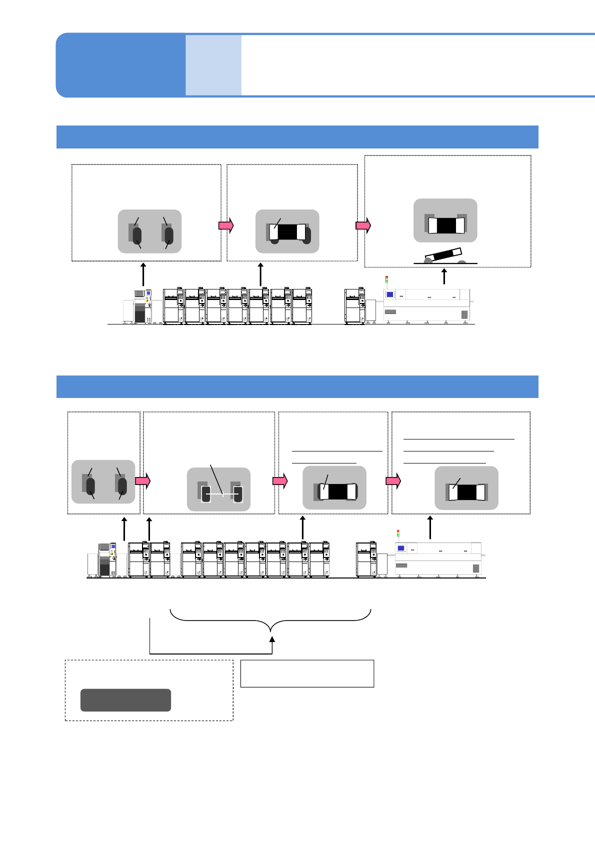
APC unsupported line example
Land
Solder
After solder printing:
Printing position misalignment
due to variations in the eland
position
After reflowing:
Nonuniform solder joint
contributes misalignment or
lifting
Part
Component placement:
Place based on the
land position
Misalignment
Lifting
APC-compliant line example (Component placement position correction)
Land
Solder
After solder
printing
Solder inspection:
Inspection and position
measurement of solder
Applicable placement
position
Part
Component
placement:
Placed based on the
solder position
After reflow:
Component moves to the
land position by self-
alignment effect
1)
Part
●Placement position correction data
●Placement skip control data
Feed-forward
communication
1) The condition of solder printing or component may disable the self-alignment.
2) An amount of correction of the placement position output from the solder inspection process is sent to
the placement / component inspection process on the downstream machine.
8-1-2-1
Solder inspection
standard
2)
・・・
Printing
Placement
Component
inspection
Reflow
・・・
Printing Placement Component
inspection
ReflowSolder
inspection
NPM-W2 EJM7DJ-MB-08O-00
8-1-2-2
APC
system
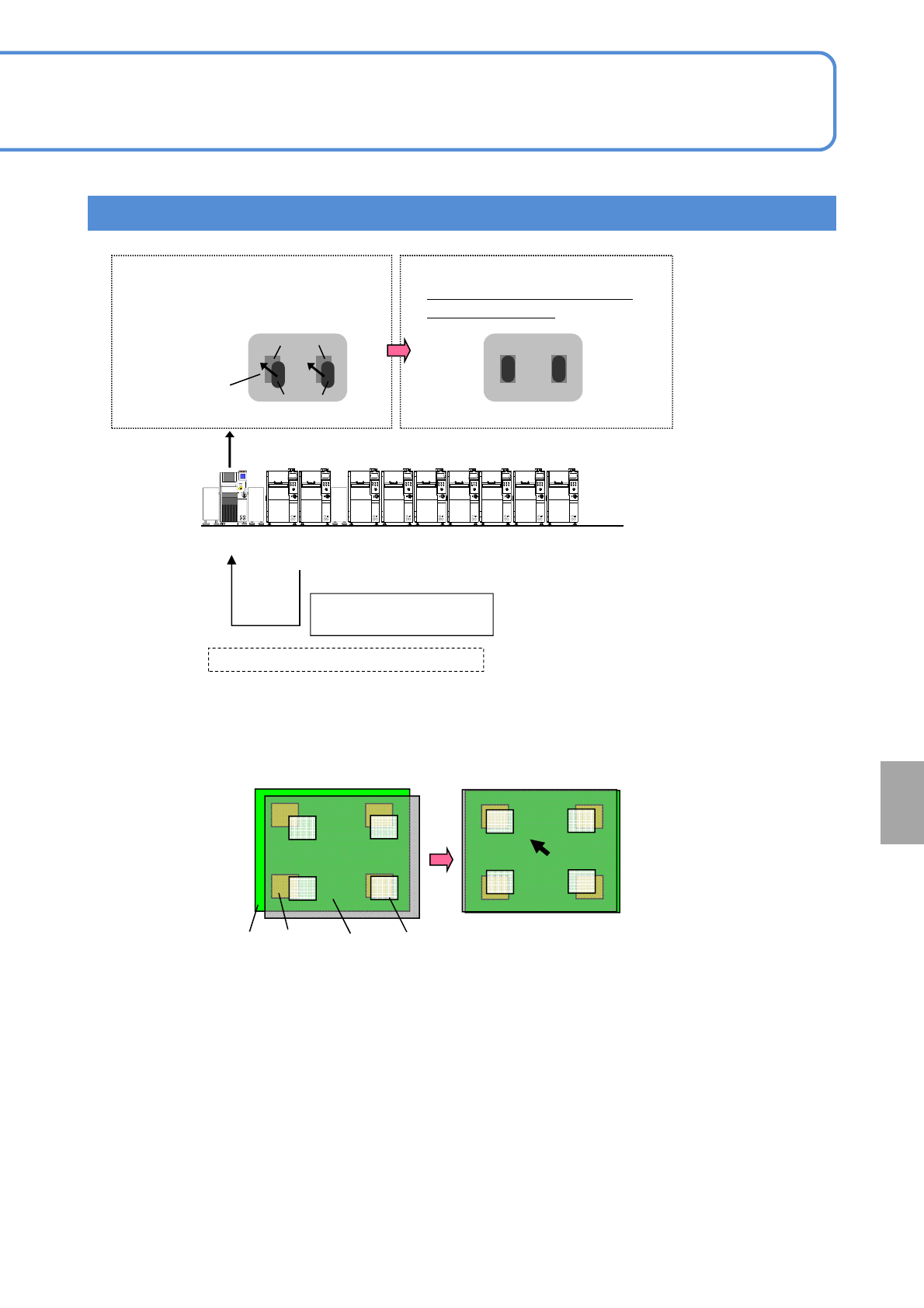
APC-compliant line example (solder printing position correction)
Solder printing:
Calculates a correction amount
from the solder position data
Solder printing:
Corrects the solder position to
the proper position
●Printing solder position / Area data
Feedback
communication
*2)
Proper printing
position
*1)
*1) Although the solder (printing mask) position to be corrected shall be the minimum solder
misalignment amount of whole PCB, misalignment still exists due to dimension error between PCB
and mask which cannot be handled by correction.
Mask position
before correction
Mask position after
correction
PCB Land Mask Aperture
*2)Solder position / area data output by the solder inspection process is sent to the solder printing
process in the upstream side.
Land
Solder
・・・
Printing PlacementSolder
inspection
NPM-W2 EJM7DJ-MB-08O-00
Over-
view
Line example and APC
system 2
Operating procedure
8-1-2
8-1-2-3
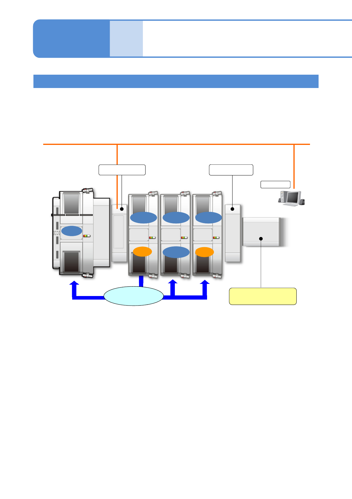
System model chart (when NPM inspection head is used)
This section describes the standard configuration of the system using APC.
● The following illustration shows an example of a PCB, that an inspection result of solder inspection (SPI)
or component inspection (AOI) results in defects, stops at the last conveyor. APC can also be installed
right after each inspection machine. Please ask specification if you are desired to do so.
● License of APC system is required per machine which generates or receives the APC correction data.
1) The following options are required.
FA computer, HUB unit, Power supply unit
2) Customer provides the conveyors.
NPM-DGS
装着装着
装着装着
SPISPI
PlacementPlacement
PrintingPrinting
Ejection conveyor
2)
Conveyor L
1)
APC correction data
AOIAOI
PlacementPlacementPlacementPlacement
PlacementPlacement
Conveyor R