N7201A616E00_0317.pdf - 第651页
NPM-W 2 EJM7DJ-MB-08O-00 ■ Setting items by a component Setting item Description APC contro l switch Placement control X direction correction Y direction correction Angle correction Choose wheth er control (correctio n) …
NPM-W2 EJM7DJ-MB-08O-00
System
function
details
Operating procedure
8-2-2
8-2-2-1
■Setting items by a PCB
Explains the setup method per PCB or component basis.
●Ethernet conducts the communication between machines.
●When an inspection machine manufactured by other companies is used, see the operating instruction of
[Other company’s interface software].
Setting item Description
Placement control Choose [ON] to control the placement position with APC.
Inspection control Choose [ON] to control the inspection position with APC.
(Inspects components based on the APC control position.)
Correction mode Placement point unit:
●The correction value measured for each placement point is applied for
each placement point.
●The correction amount of the component, whose [APC control switch] is
OFF, becomes zero.
●The correction amount of the component, of which [APC control switch]
is ON and also which failed to be measured, averages that of other
components measured successfully.
Pattern unit:
●After measuring the components, of which the measurement control is
set to [Target], within each pattern, the average value of their correction
amount is applied for other components belonging to each pattern.
●With no component to be measured, the correction amount of all the
components becomes zero.
●If there is no component to be measured in a pattern, or if all the
components in a pattern failed to be recognized, the correction amount
of all the components belonging to the pattern averages that of the
components measured successfully in other patterns.
Pattern unit (2 point correction):
●Using the correction value of more than 2 components selected from the
same pattern, the correction amount, obtained by using the rotation of
the PCB recognition correction and the calculating method of the PCB
expansion and contraction correction, is applied for the components
included in the pattern.
●As is the case with the PCB recognition, a minimum of a pair of 2
components, located on cater corner, is set for each pattern as a
correction reference.
Average value
application for a
misalignment amount
during placement unit
correction
Choose [ON] and input the setting value if the average value
misalignment amount is set.
Apply the average value of the pattern if the placement position correction
value exceeds this value, which occurs as a measurement error.
Various settings 1
Feed-forward function
NPM-W2 EJM7DJ-MB-08O-00
■Setting items by a component
Setting item Description
APC control switch
Placement control
X direction correction
Y direction correction
Angle correction
Choose whether control (correction) is carried out for each direction or
not.
ON :Controlled (Corrected)
OFF : Not controlled (not collected)
Ratio of correction amount
Electrode direction
Non-electrode direction
Angle direction
Set the ratio of the correction value for each direction. 0-100 [%]
●The correction value is limited by the value multiplied this ratio to
the measurement result.
Threshold of correction value
Electrode direction
Non-electrode direction
Angle direction
Set the threshold of the correction value for each direction. [mm]
●If the measurement result exceeds this value, the correction value
is limited to this value.
Feed-forward offset
X-direction
Y-direction
Set the offset for feed forward.
●Place the component to the position where this value is added to
the solder position of the measurement result.
Measurement control Non-target: It is not target for measurement control.
Target: It is target for measurement control.
●If the measurement mode is [By pattern] or [By pattern (correction
at 2 points)], [Target] of the component for one or two point s must
be set per pattern.
Individual correction No: Individual correction does not carried out
Yes: Individual correction is carried out
●If the measurement mode is By pattern] or [By pattern (Correction
at 2 points)], the self solder position measurement result is applied
to the correction value for the specified component.
Placement standard Solder: Measure by solder placement basis.
Land: Measure by land placement basis.
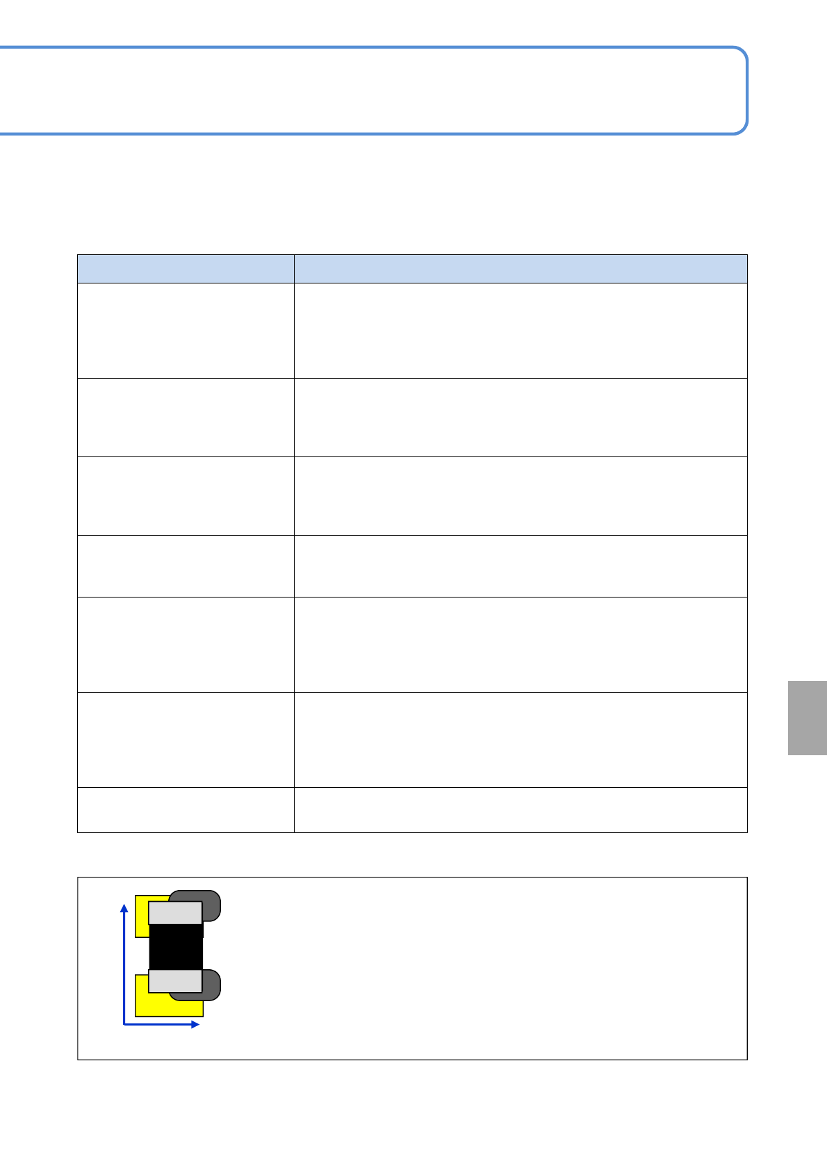
Electrode direction:
Placed to a position completely (100%) responded to the position where a
solder joint is misaligned
Non-electrode direction :
Placed to a position half (50%) responded to the position where a solder
joint is misaligned
●A component with electrodes on both sides such as a minitrans or SOP are
applicable. (QFP and BGA are inapplicable)
*1)Example when the ratio of the correction value for non-electrode direction is set to 50%
*1)
8-2-2-2
50%
100%
Non-electrode
direction
Electrode
direction
APC
system
NPM-W2 EJM7DJ-MB-08O-00
System
function
details
Operating procedure
8-2-2
8-2-2-3
Various settings 2
■Setting items by a PCB
●Ethernet conducts the communication between machines.
●The production data setting of the printing machine is also required. For details, see the operating manual
[NPM-DGS SP data editor].
●When the machine manufactured by other companies is used, see the operating instruction [Other
machine’s Inspection machine interface software].
Setting item Description
Printing control Choose [ON] to control the printing position with APC.
Feedback function