N7201A616E00_0317.pdf - 第653页
NPM-W 2 EJM7DJ-MB-08O-00 8-2-2 -4 APC system

NPM-W2 EJM7DJ-MB-08O-00
System
function
details
Operating procedure
8-2-2
8-2-2-3
Various settings 2
■Setting items by a PCB
●Ethernet conducts the communication between machines.
●The production data setting of the printing machine is also required. For details, see the operating manual
[NPM-DGS SP data editor].
●When the machine manufactured by other companies is used, see the operating instruction [Other
machine’s Inspection machine interface software].
Setting item Description
Printing control Choose [ON] to control the printing position with APC.
Feedback function

NPM-W2 EJM7DJ-MB-08O-00
8-2-2-4
APC
system
NPM-W2 EJM7DJ-MB-08O-00
System
function
details
Operating procedure
8-2-3
Precautions on
operation 1
The correction angle is calculated from angle joining more than two solder center of gravity. Therefore, as
for the component such as smaller number of electrode of chip components and narrower distance
between electrodes, the measurement result will not be fixed and it is not appropriate for correction. We
recommend not using for these components since they are enough to correct only XY direction.
●Please use the design value for the placement coordinate data or PCB recognition coordinate data.
Regarding A (angle) correction of a placement position
Confirmation method of APC applied PCB
8-2-3-1
■APC system requirements
●Bad beam of the solder inspection head is set to OFF
●Inspection of the adjustment setting is set to ON
●LNB is connected
●Forced ejection of PCB transport is set to OFF
When APC is used, PCBs being not produced should not be inserted from the inspection ejection
conveyor. Doing so may cause a PCB transport error.
If the APC system is not applied, APC system requirements might not be satisfied or configuration settings
might be set incorrectly. Please check that system requirements are satisfied and settings are set correctly.
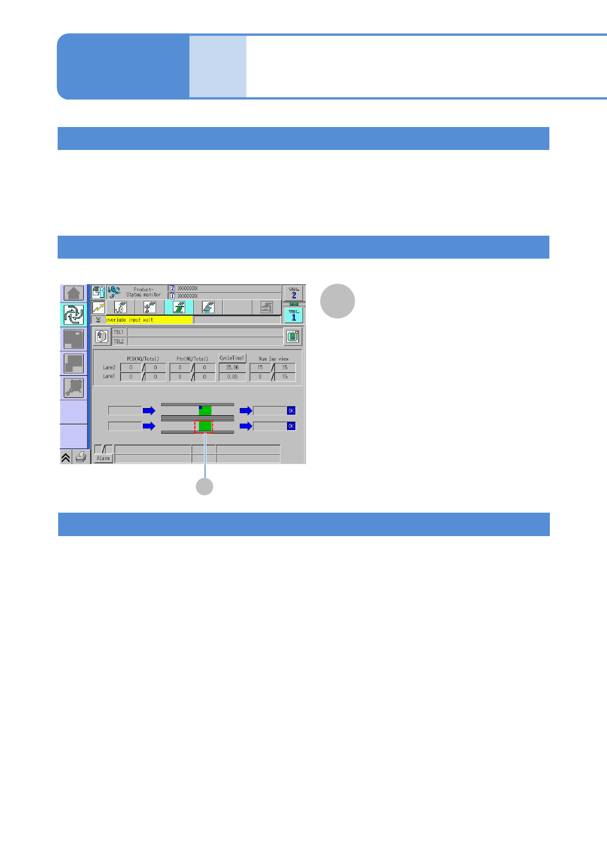
When APC is not applied
A
APC
A
APC
●It is displayed only when APC is
applied.