N7201A616E00_0317.pdf - 第659页
NPM-W 2 EJM7DE-MB-09O -00 9-1-1 -2 At a glance Basic performance Item Specification Light weight 16-nozzle head 12-nozzle head 8-nozzle head 3-nozzle head Placement angle 0 to 359 ° (It can be set in increments of 0.01 °…
NPM-W2 EJM7DE-MB-09O-00
Specifi-
cation
Machine specifications/
Basic performance 1
9-1-1-1
Operating procedure
9-1-1
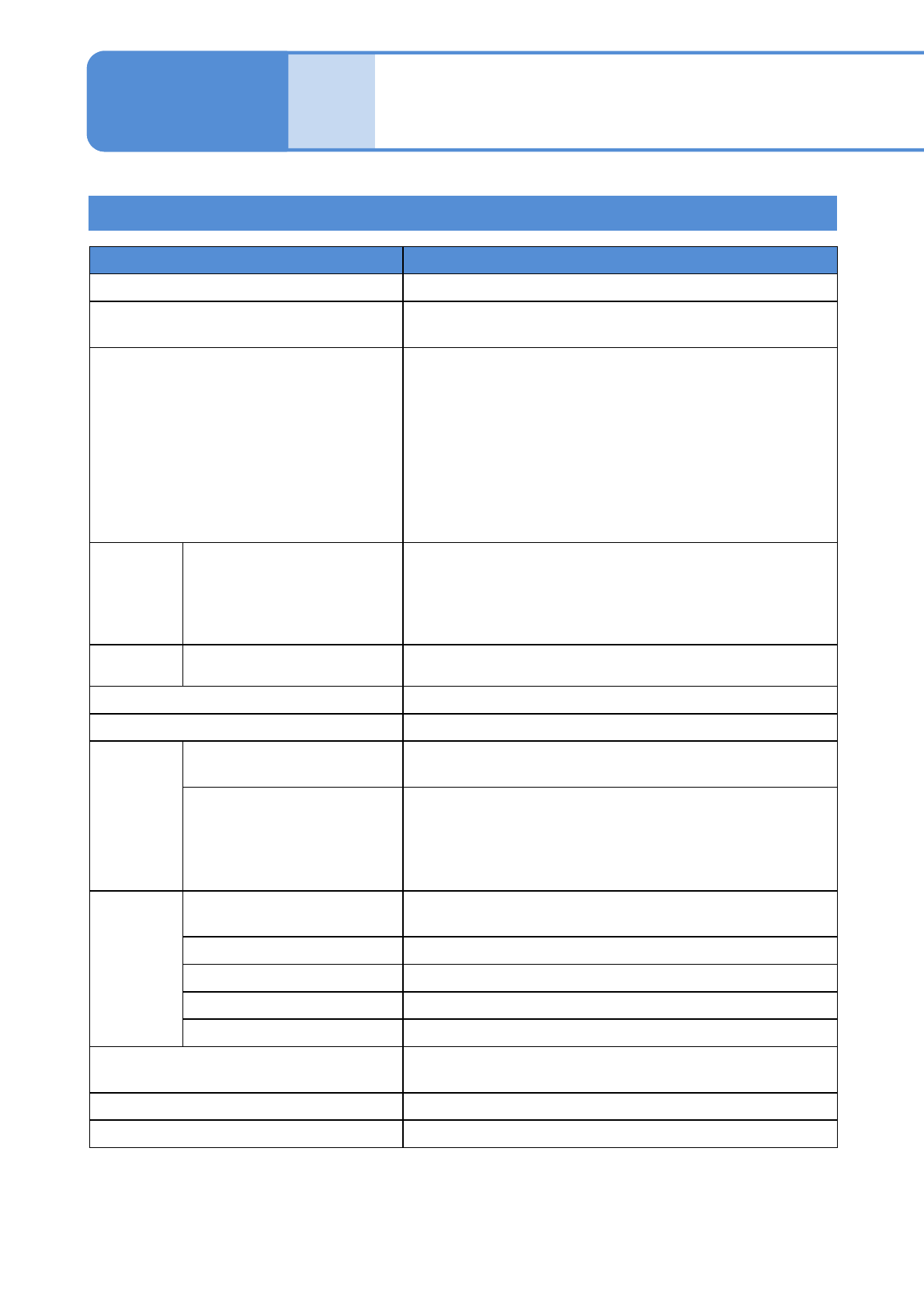
Machine specifications
Item
Specification
Control system Microcomputer system
External memory
The data is managed by LNB
3)
Approximately 1MB is required for a piece of data
Program data
1)
Number of placement points: Max. 10 000 points /machine
(Placement coordinates, recognition mark coordinates, bad
mark coordinates and PCB height measurement points are
included.)
* In the case of production in dual lane mode, it is the total
number of placement points in the front and rear lanes. In
the case where the number of placement points is more
than 10 000points/line, please consult with us separately.
Also, about the line mixed with the CM/DT series, please
consult with us separately.
Power
source
Machine body
Normal service power source: Three-phase AC 200 / 220
±10 V, Three-phase AC 380 / 400 / 420 / 480 ±20 V
Frequency: 50 /60 Hz
Peak current value during operation: 40 A (rated voltage AC
200 V)
Rated
capacity
Machine body 2.8 kVA
Supply air pressure 0.5 to 0.8 MPa (working air pressure: 0.500 to 0.505 MPa)
Supply air volume 200 L / min (A.N.R.)
Outside
dimensions
Main body only
W 1 280 D 2 465 H 1 444 mm
(The signal tower and the touchscreen are not included)
With a supply unit
■When a feeder cart
4)
is connected
W 1 280 D 2 465 H 1 444 mm
(The signal tower and the touchscreen are not included)
■When a tray feeder
4)
is connected
W 1 280 D 2 570 H 1 444 mm
Mass
2)
Main body
2 470 kg per unit (Mass of 190 kg per unit of a standard
configuration feeder cart
4)
is not included)
Feeder cart
4)
190 kg per unit
Single tray feeder
4)
200 kg per unit
Twin tray feeder
4)
360 kg per unit
Standard configuration
2 850 kg (one main unit and two feeder carts
4)
)
Environmental condition
Temperature: 10 to 35C
Humidity: 25 to 75% RH (no condensation)
Altitude 1 000 m or less above sea level
Noise < 70 dB (A)
1)
This machine can modify only some data. The data is created by NPM-DGS.
NPM-DGS is software creating production data for NPM (not included in this product)
2)
Mass of the main body excluding the optional units.
3)
LNB (Line network box) manages the production data shared in the line.
4)
Options
NPM-W2 EJM7DE-MB-09O-00
9-1-1-2
At
a glance
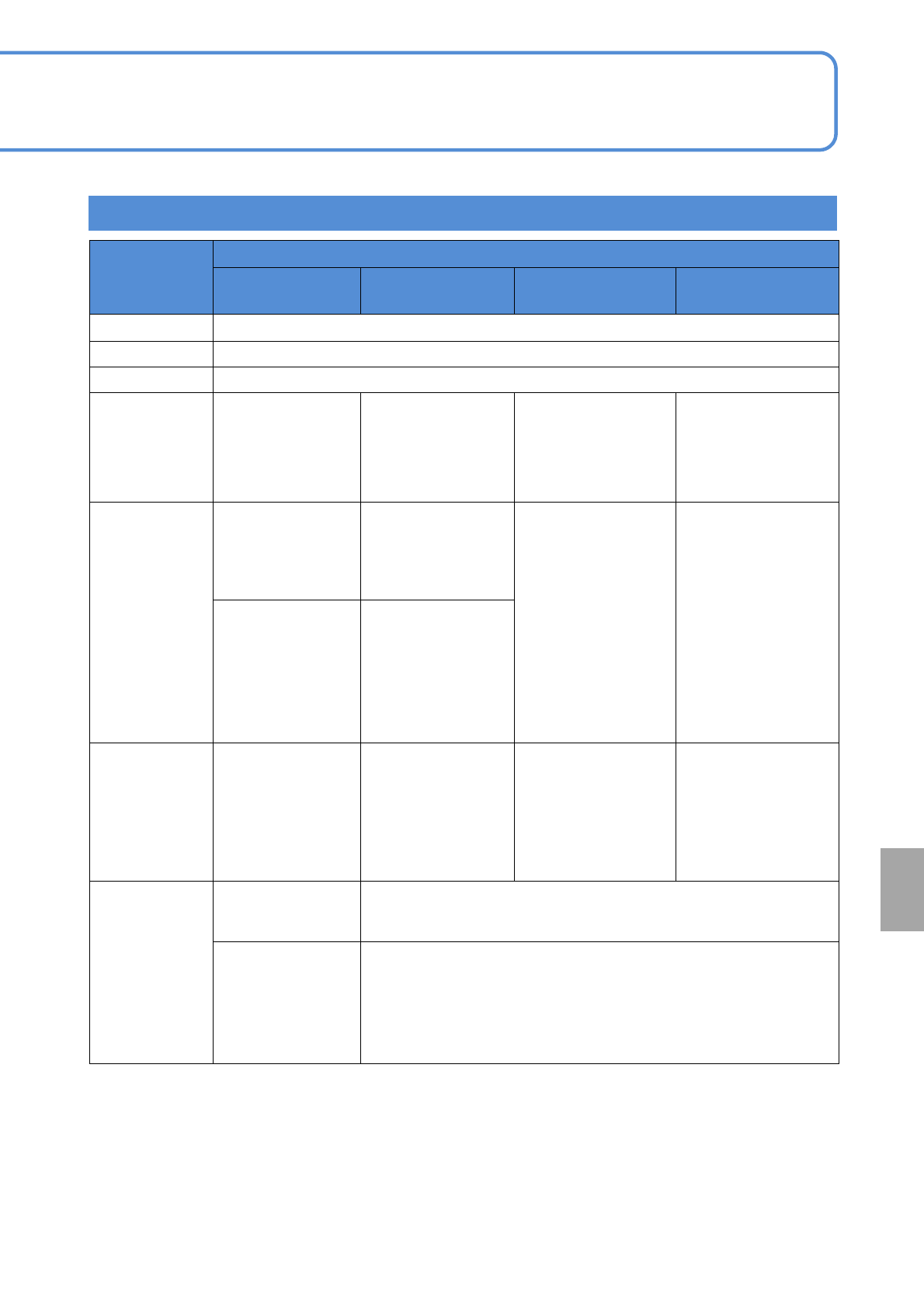
Basic performance
Item
Specification
Light weight
16-nozzle head
12-nozzle head 8-nozzle head 3-nozzle head
Placement angle 0 to 359 °(It can be set in increments of 0.01°)
Placement range
(→P.9-1-4 ‘Applicable PCB specifications’)
PCB flow direction (→P.9-1-2 ‘PCB flow direction’)
Placement tact
time
*1)
(under optimum
conditions)
0.047 s per chip
(High production
mode :ON)
0.051 s per chip
(High production
mode :OFF)
0.056 s per chip
(High production
mode :ON)
0.058 s per chip
(High production
mode :OFF)
0.090 s per chip
0.225 per chip
(for QFP, 0.288 s)
Placement tact
time
*1) *2)
(under optimum
conditions)
■High production
mode :ON
±0.04 mm: Cpk ≧1
(0402, 0603, 1005
chip)
■High production
mode :ON
±0.04 mm: Cpk ≧1
(0402, 0603, 1005
chip)
±0.03 mm: Cpk ≧1
(0402, 0603, 1005
chip)
±0.05 mm: Cpk ≧1
(QFP:12 × 12 mm
or less)
±0.03 mm: Cpk ≧1
(QFP:12 × 12
to 32 × 32 mm or
less)
±0.03 mm: Cpk ≧1
(QFP)
■High production
mode :OFF
±0.03 mm: Cpk ≧1
(03015*
5)
, 0402,
0603, 1005 chip)
±0.025 mm: Cpk ≧1
(1005 chip) *
6)
■High production
mode :OFF
±0.03 mm: Cpk ≧1
(0402, 0603, 1005
chip)
Target component
Component
dimensions
( 03015 chip)
*5)
to 6 6 mm
Component
thickness: Max. 3
mm
Component
dimensions
( 0402 chip)
to 12 12 mm
Component thickness:
Max. 6.5 mm
Component dimensions
( 0402 chip)
to 32 32 mm
Component thickness:
Max. 12 mm
Component dimensions
( 0603 chip)
to 150 25 mm
(opposite side152.1 mm
or less)
Component thickness:
Max. 30 mm
Mass: Max. 30 g
PCB change time
Single conveyor
2.3 s (L 350 mm or less)
4.4 s (L 350 mm or over to 450 mm or less)
5.2 s (L 450 mm or over to 750 mm or less)
*3)
Dual conveyor
・Dual lane mode: 0 s
*3)
(If the cycle time is less than PCB changeover time, the time shall not
be 0 s).
・Single lane mode
*4)
2.3 s (L 350 mm or less)
4.4 s (L 350 mm or over to 450 mm or less)
5.2 s (L 450 mm or over to 750 mm or less)
*3)
*1) The values may vary with the type of component.
*2)
This is the case where the placement angle is 0°, 90°, 180°, or 270°. They may be affected by
rapid changes in ambient temperature.
*3) When the PCB is transported without placing the parts while the extension conveyor is installed
between machines.
*4) When PCBs are produced in single lane mode, the PCB support block (option) for single lane mode is
required.
*5) To support 03015 components, see (→P.9-1-11 ‘03015 placement support’)
*6)
To support ±0.025 mm, see (→P.9-1-12 ‘Placement accuracy ±0.025 mm support’)
NPM-W2 EJM7DE-MB-09O-00
Specifi-
cation
Machine specifications/
Basic performance 2
Operating procedure
9-1-1
9-1-1-3
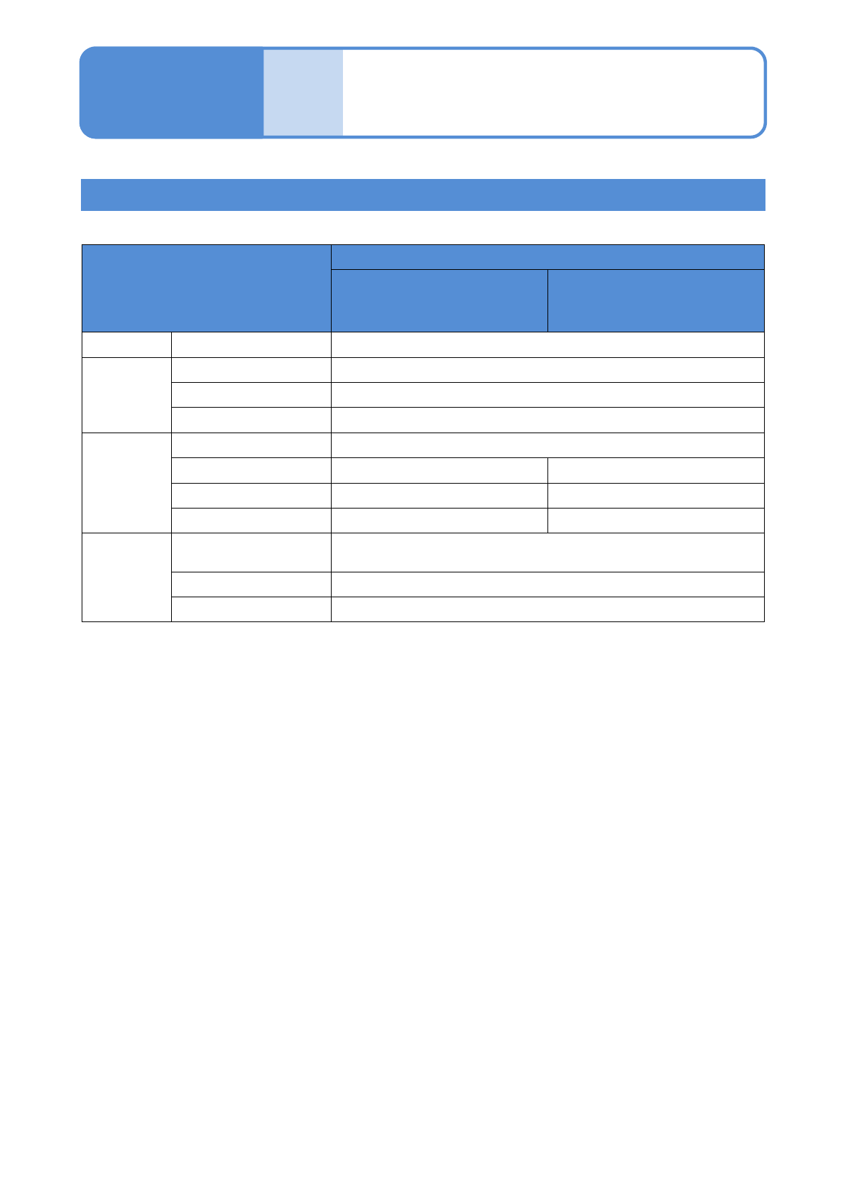
■Component recognition camera specifications
Basic performance
Item
Multi-recognition camera
*1)
Type 1 (2D measurement)
/ Type 2 (thickness
measurement)
*2)
Type 3 (3D measurement)
Chip Outside dimension
0402,03015
*3)
to
QFP
SOP
Outside dimension
5 5 to 45 45 mm
Minimum lead pitch
0.4 mm
Minimum lead width
0.2 mm
BGA
CSP
Outside dimension
5 5 to 45 45 mm
Minimum ball pitch
0.3 mm 0.5 mm
Minimum ball diameter
0.15 mm 0.25 mm
Minimum ball height
--- 0.25 mm
Connector
Outside dimension
to 100 (L) 90 mm (W)
Opposite side134.5mm
Minimum lead pitch
0.5 mm
Minimum lead width
0.2 mm
*1 ) The values may vary depending on head specifications.
*2 ) Thickness can be measured by 03015 to Min Tr/Di.
*3 ) For supporting a 03015 component. (→P.9-1-11 ‘Supporting 03015 placement’)