N7201A616E00_0317.pdf - 第686页
NPM-W 2 EJM7DE-MB-09O -00 8-nozzle head 9-1-6 -3 Nozzle No. Shape (mm) Target componen t s (Ex.) 240C 240CN 3216R, C 4532R, C TAN-X,B,C,D Al electrolytic- A,B,C 140 140N TAN-D AI electrolytic- D SOP SOJ PLCC CSP 185 185N…
NPM-W2 EJM7DE-MB-09O-00
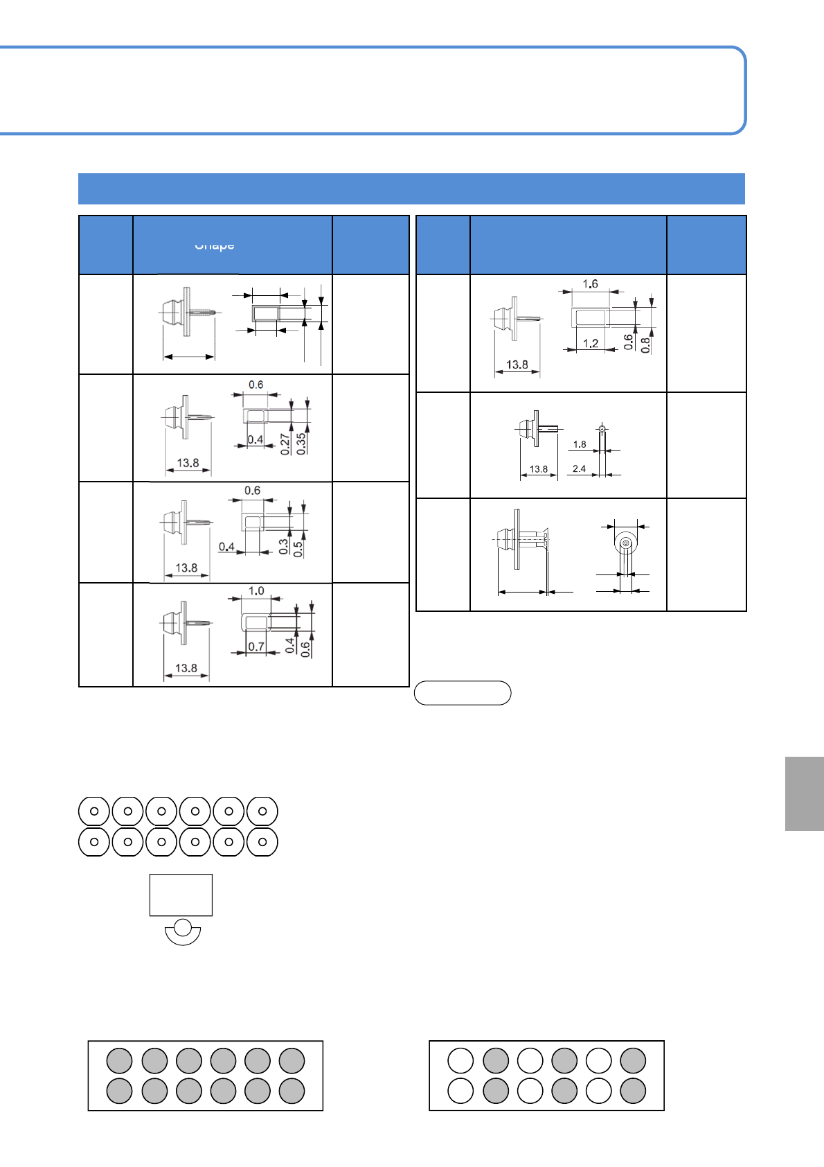
12-nozzle head
9-1-6-2
Nozzle
No.
Shape (mm)
Target
component
s (Ex.)
235CS
235CSN
1608R, C
2012R, C
3216R, C
SS-Mini Tr, Di
S-Mini Tr, Di
240CS
240CSN
3216R, C
4532R, C
TAN-X
140S
140SN
AI electrolytic,
SOP
Nozzle
No.
Shape (mm)
Target
component
s (Ex.)
256CS
256CSN
0402R, C
225CS
225CSN
0603R, C
226CS
226CSN
0603R, C
1005R, C
230CS
230CSN
1005R, C
1608R, C
●For the nozzle No. including ‘C’, the nozzle tip is
made of ceramic.
●For the nozzle No. including ‘N’, the 2D code is
provided on the nozzle flange supporting the 2D
code recognition in the NPM series.
●Component pickup condition
Pickup enabled with all nozzles:
0402 ≦ component range ≦ 6 6 mm
Pickup enabled with even number nozzles:
6 6 mm ≦ component range ≦ 12 12 mm
●Even though above seven types are standard for
nozzles for 12-nozzle head, they are available as
nozzles for 12-nozzle head in the CM series.
●The nozzle for 8-nozzle head and the AM100 nozzle
are not available.
●Transparency recognition may have restrictions on
component dimensions and height. (Because of
affecting components of adjacent nozzles)
NOTE
Component of 6 mm 6 mm or less
1 2 3 4 5 6
7 8 9 10 11 12
1 2 3 4 5 6
7 8 9 10 11 12
(Only for reflecting recognition)
■Pickup component dimensions and nozzle arrangement
( ●: Pickup enabled, ○: Pickup disabled)
●Pickup enabled component:
6 mm or larger 6 mm or larger to 12 12 mm
(6 6 < A A ≦ 12 12)
At
a glance
13.8
4
0.2
1.5
2.5
0.39
0.32
0.17
0.3
Nozzle arrangement
●Pickup enabled component: 6 6 mm or less
123456
789101112
Head
camera
(Condition seen from the top)
13.8
NPM-W2 EJM7DE-MB-09O-00
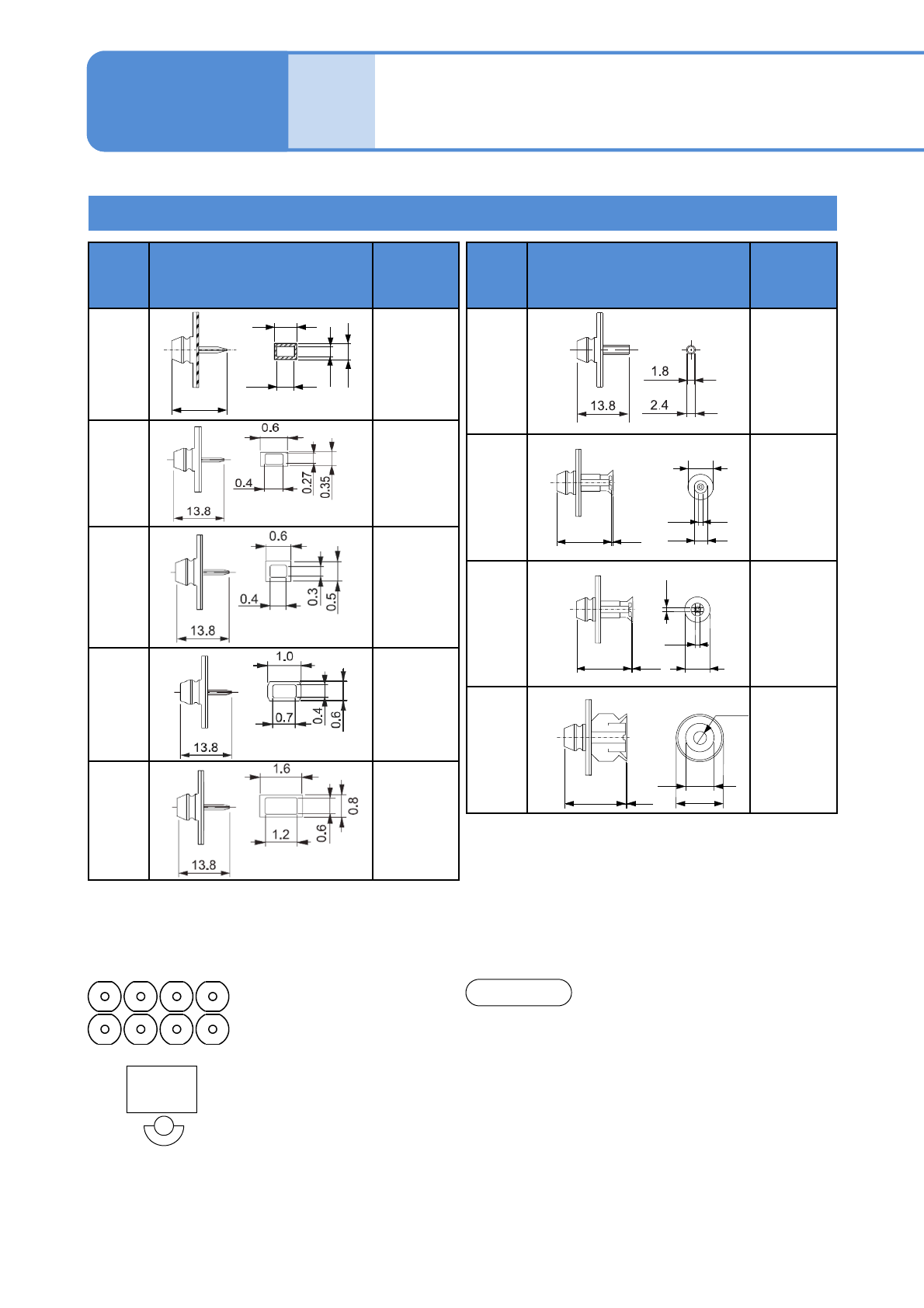
8-nozzle head
9-1-6-3
Nozzle
No.
Shape (mm)
Target
component
s (Ex.)
240C
240CN
3216R, C
4532R, C
TAN-X,B,C,D
Al electrolytic-
A,B,C
140
140N
TAN-D
AI electrolytic-
D
SOP
SOJ
PLCC
CSP
185
185N
SOP
QFP
PLCC
BGA
~
18 x18 mm
199
199N
SOP
QFP
PLCC
BGA
~
32x32 mm
●Even though above nine types are standard for
nozzles for 8-nozzle head, they are available as
nozzles for 8-nozzle head in the CM series.
●They are not available as nozzles for light weight
16-/16-/12-nozzle head.
●The AM100 nozzle is not available.
Specifi-
cation
Nozzle specifications 2
NOTE
Operating procedure
9-1-6
●For the nozzle No. including ‘C’, the nozzle tip is made of ceramic.
●For the nozzle No. including ‘N’, the 2D code is provided on the nozzle flange supporting the 2D code
recognition in the NPM series.
.
13.8
0.3
0.39
0.32
0.17
13.8
6
1.5
0.3
1.5
13.8
4
0.2
1.5
2.5
13.8
10
Φ2.4
0.1
6
Nozzle
No.
Shape (mm)
Target
component
s (Ex.)
256C
256CN
0402R, C
225C
225CN
0603R, C
226C
226CN
0603R, C
1005R, C
230C
230CN
1005R, C
1608R, C
235C
235CN
1608R, C
2012R, C
3216R, C
SS-Mini Tr, Di
S-Mini Tr, Di
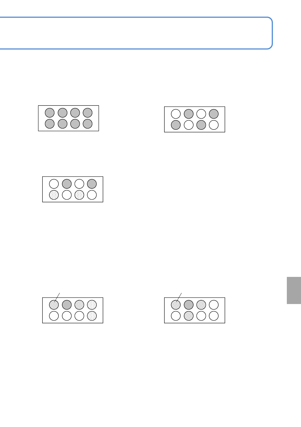
1234
5678
Head
camera
(Condition seen from the top)
NPM-W2 EJM7DE-MB-09O-00
9-1-6-4
1 2 3 4
5 6 7 8
1 2 3 4
5 6 7 8
■Pickup component dimensions and nozzle arrangement
( ●: Pickup enabled, ○: Pickup disabled)
*When a component exceeds the size of 24 24 mm, install a recognition nozzle of 4 mm or less in
nozzle diameter around its nozzle arrangement position.
●Pickup enabled component:
12 12 mm or less
(A A ≦ 12 12)
●Pickup enabled component:
18 18 mm to 24 24 mm
(18 18 < A A ≦ 24 24)
●Pickup enabled component:
12 12 mm to 18 18 mm
(12 12 < A A ≦ 18 18)
1 2 3 4
5 6 7 8
Components of 12 12 mm or less can be
picked up on ⑤ and ⑦.
Recognition nozzle(φ4 mm or less): ①, ③
1 2 3 4
5 6 7 8
●Pickup enabled component:
Component of 24 24 mm to 28 28 mm
(24 24 < A A ≦ 28 28)
Components of 12 12 mm or less can be
picked up on ④ and ⑧.
Recognition nozzle(φ4 mm or less): ①, ③,
⑥
1 2 3 4
5 6 7 8
●Pickup enabled component:
Component of 28 28 mm to 32 32 mm
(28 28 < A A ≦ 32 32)
At
a glance