N7201A616E00_0317.pdf - 第695页
NPM-W 2 EJM7DE-MB-09O -00 9-1-6 -12 Dispensing direction 0 ° -90 ° 90 ° 1-point disp ensing / Drawing dispensing *1) 4.9 5.65 4.1 2-point dispensin g 4.9 (Partially 5.4) 5.65 5.63 4-point dispensin g 4.9 5.9 5.9 ■ Restri…
NPM-W2 EJM7DE-MB-09O-00
Specifi-
cation
Nozzle specifications 6
Dispensing nozzle (option) 2
9-1-6-11
Operating procedure
9-1-6
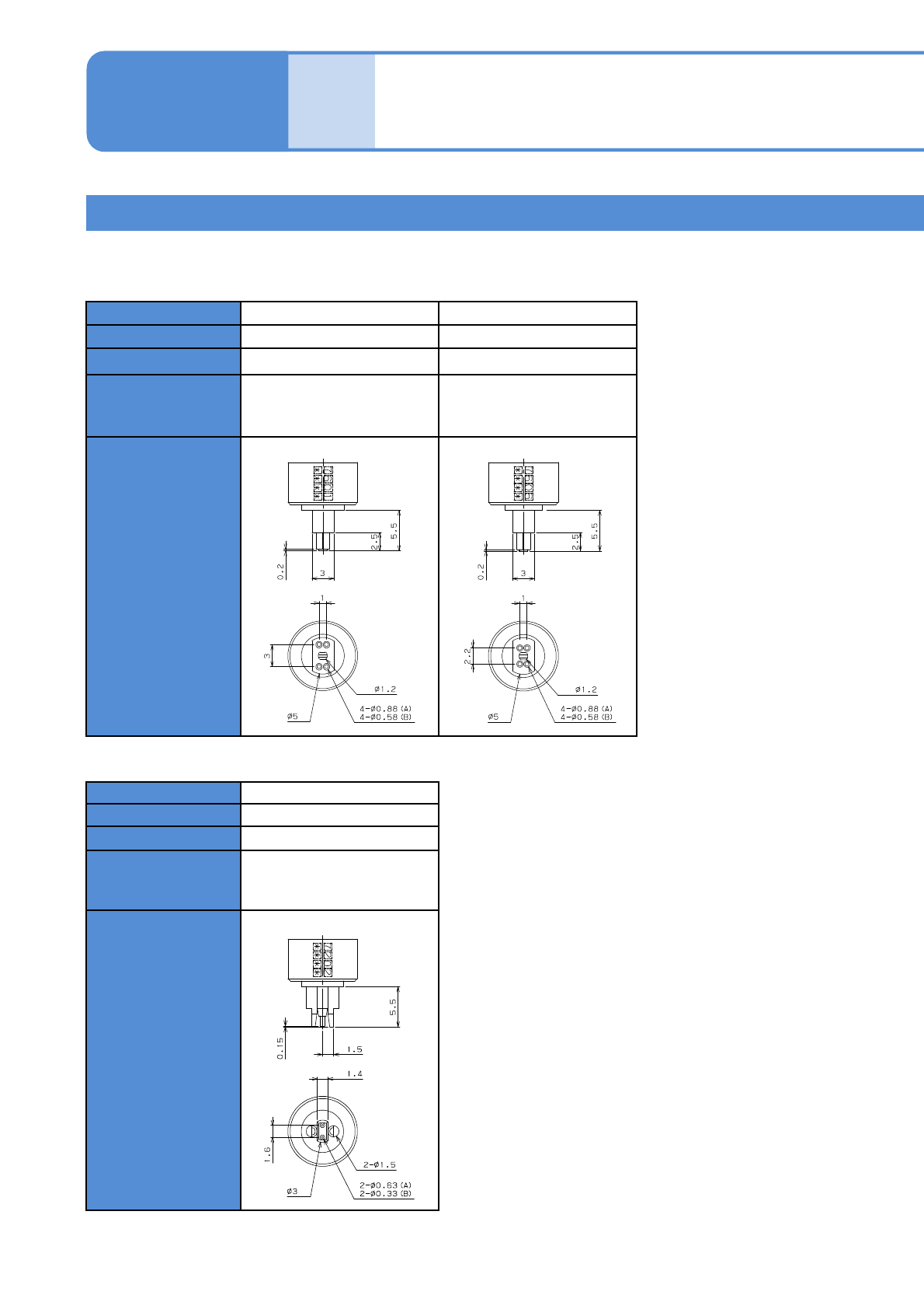
■4-point nozzle
Nozzle No. 7601 7606
Type Dot dispense Dot dispense
Diameter (guide)
φ0.8 to φ1.2 mm φ0.8 to φ1.2 mm
Component
(representative
example)
Large type component Large type component
Shape
(Unit: mm)
Nozzle No. 7202
Type Dot dispense
Diameter (guide)
φ0.6 to φ1.1 mm
Component
(representative
example)
For calibration
Shape
(Unit: mm)
(A: Outer Diameter B:Inner Diameter)
■Calibration nozzle
(A: Outer Diameter B:Inner Diameter)
NPM-W2 EJM7DE-MB-09O-00
9-1-6-12
Dispensing direction
0° -90° 90°
1-point dispensing /
Drawing dispensing
*1)
4.9 5.65 4.1
2-point dispensing 4.9 (Partially 5.4) 5.65 5.63
4-point dispensing 4.9 5.9 5.9
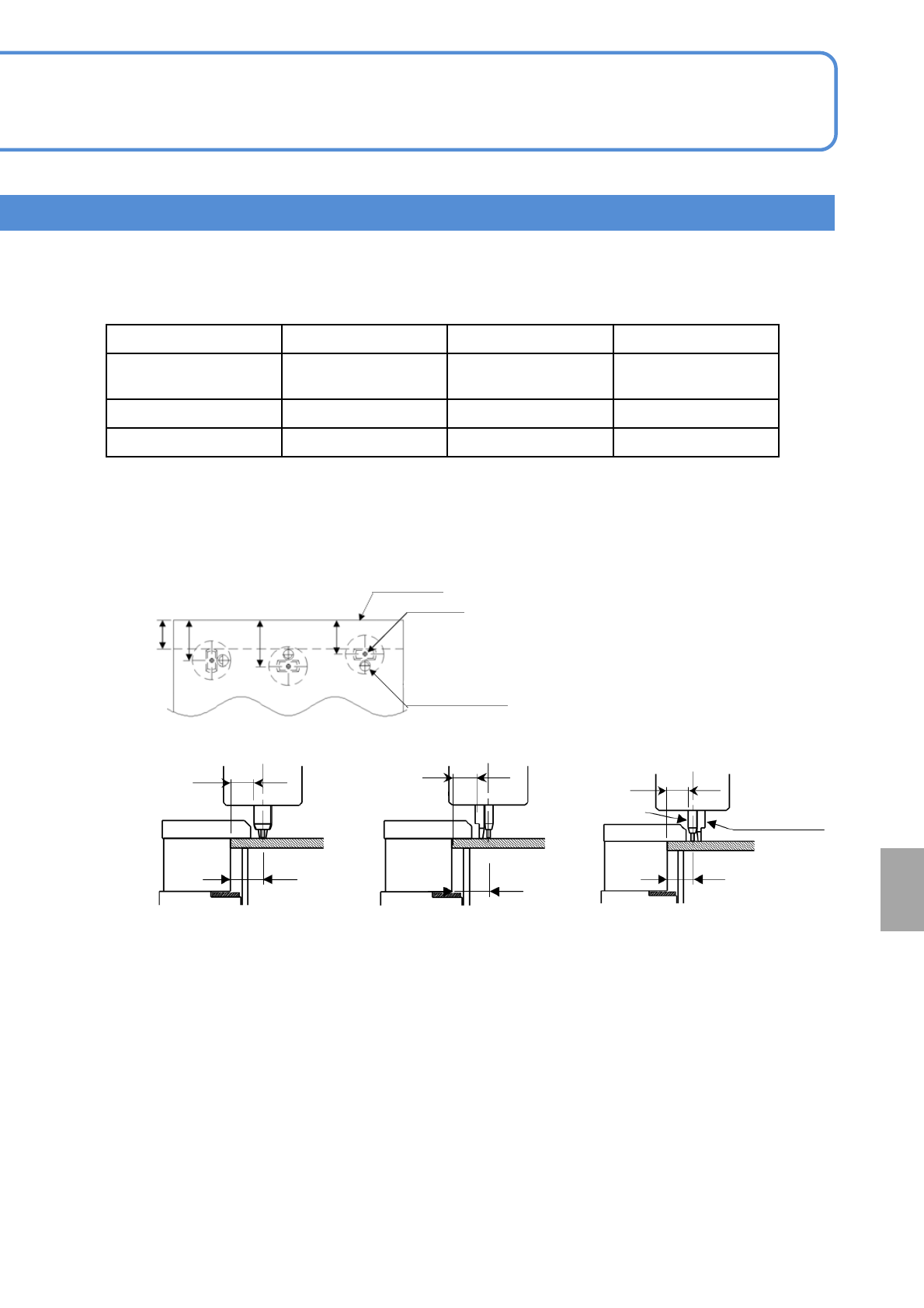
■Restriction of dispensing area
Dispensing disabled area from the PCB edge (PCB top surface; rear side) (Y-direction) (Unit:mm)
●In the case of the near side of the PCB undersurface, because the stopper position is inverted in Y-
direction, the values for -90° switch places with those for 90° in the above table of dispensing
disabled distances.
*1) The drawing dispensing nozzle is the same condition as “0°” of the 1-point nozzle.
1) 1-point nozzle / Drawing dispensing nozzle
*2)
(Unit:mm)
( 0°)
Dispensing disabled area
3.4
4.9
( -90°)
Dispensing disabled area
3.4
5.65
(90°)
Dispensing disabled area
3.4
4.1
Stopper edge
PCB edge
Stopper tip
4.1
5.65
4.9
Dead space
3.4
( 0°)( -90°)
(90°)
Nozzle
At
a glance
NPM-W2 EJM7DE-MB-09O-00
9-1-6-13
Specifi-
cation
Nozzle specifications 7
Dispensing nozzle (option) 3
Operating procedure
9-1-6
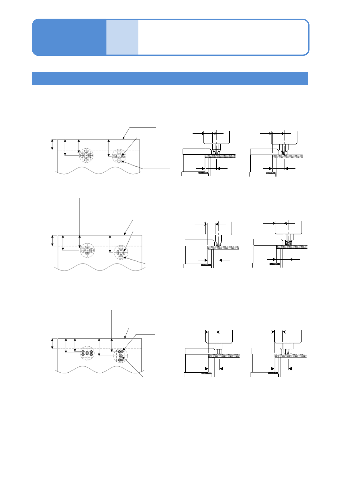
2) 2-point nozzle (Unit:mm)
Dispensing
disabled area
3.4
Dispensing
disabled area
3.4
5.4
5.65
( 0°)( -90°, 90°)
( 0°)
PCB edge
5.65
4.9
Dead space
3.4
Stopper tip
Nozzle
3.65 (7223)
3.8 (7222)
3.9 (7236)
4.0 (7201,7204)
4.1 (7202)
( -90°, 90°)
①7224 nozzle
PCB edge
5.65
5.4
Dead space
3.4
Stopper tip
Nozzle
4.4
Dispensing
disabled area
3.4
Dispensing
disabled area
3.4
4.9
5.65
( 0°)( -90°, 90°)
3) 4-point nozzle (Unit:mm)
②Other nozzles
( 0°)
PCB edge
5.9
4.9
Dead space
3.4
Stopper tip
Nozzle
( -90°, 90°)
4.4
3.9 (7601)
4.3 (7606)
Dispensing
disabled area
3.4
Dispensing
disabled area
3.4
4.9 5.9
( 0°)( -90°, 90°)
●The dispensing disabled area applies when mark recognition offset and nozzle offset are 0.
If correction or nozzle offset is performed the dispensing disabled area may be wider.