N7201A616E00_0317.pdf - 第704页
NPM-W 2 EJM7DE-MB-09O -00 9-1-9 -3 Specifi- cation A utoma tic suppor t pin c hange 2 More tha n the followin g space is required be tween the suppor t pin (for automatic c hange) and a component. (Unit: mm) PCB Support …
NPM-W2 EJM7DE-MB-09O-00
9-1-9-2
1. Do not apply strong impact on the support pin (for automatic change) such as dropping. It may deform
the pin. Also do not use a deformed support pin (for automatic change).
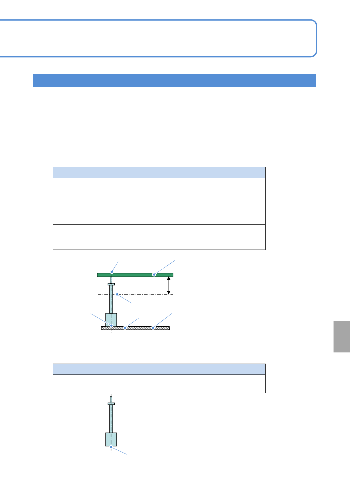
2. The support pin (for automatic change) uses a magnet.
It may have an affect on an electrical component being mounted (e.g. inductor). Looking at electrical
component specification and magnetic flux density under the condition described table below, be careful
while handling the support pin.
Symbol Location Magnetic flux density
A
PCB top surface 1.5 mT(15 G)
B
Bottom of a PCB 28mm 6 mT(60 G)
C
Support block top surface around the
support pin (for automatic change)
50 mT(500 G)
D
Between bottom surface of the support pin
(for automatic change) and support block
top surface
500 mT(5000 G)
●Magnetic flux density (reference value)
Installation condition
28 mm
PCB
A
B
D
C
PCB-support block
(for automatic change)
Symbol Location Magnetic flux density
E
Support pin (for automatic change) bottom
surface
320 mT(3200 G)
Single pin condition
E
At
a glance
Handling precautions
NPM-W2 EJM7DE-MB-09O-00
9-1-9-3
Specifi-
cation
Automatic support pin
change 2
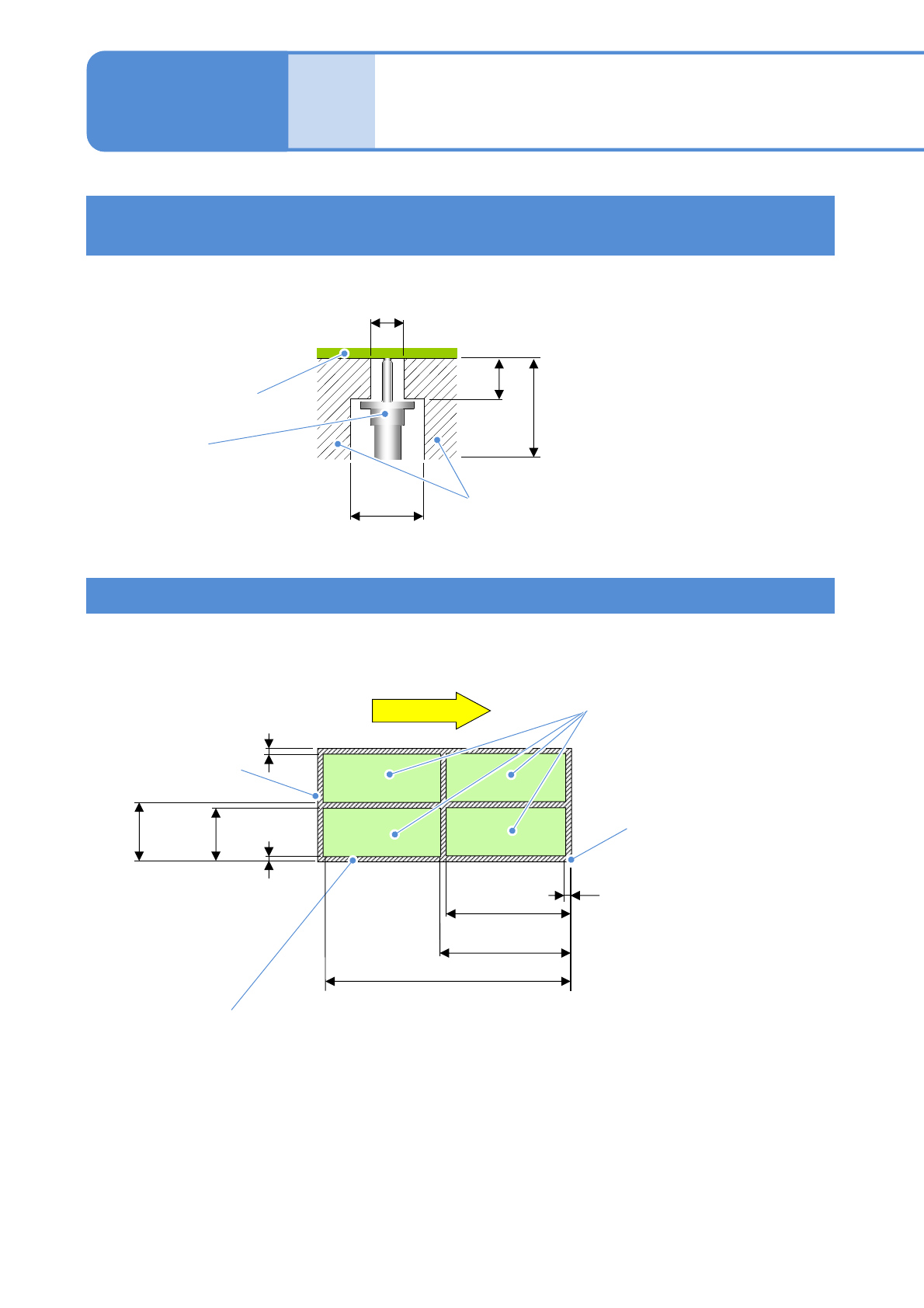
More than the following space is required between the support pin (for automatic change) and a
component. (Unit: mm)
PCB
Support pin
(for automatic change)
φ15
28
φ8 (There should be no slit)
Area where a component
enables to exist
6
Operating procedure
9-1-9
■Single conveyor (Unit: mm)
PCB
outline
Not arrangeable area
Arrangeable area
PCB flow
Reference
more than
14.5
more than
32.5
less than 735.5
less than 414.5
less than
264
less than 335.5
less than
286
more than
32.5
Arrangement position condition of the support pins (for
automatic change)
Arrangement area of support pins (for automatic change)
●Do not arrange the support pin on the slit.
NPM-W2 EJM7DE-MB-09O-00
9-1-9-4
At
a glance
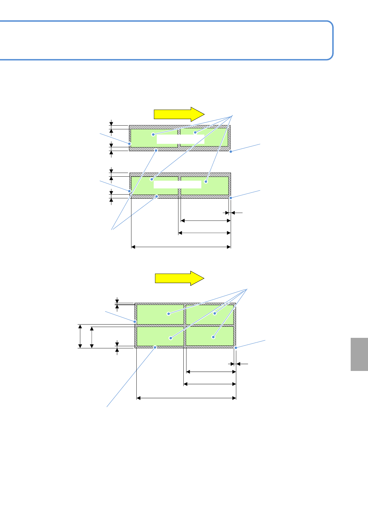
①Dual lane mode
■Dual conveyor (Unit: mm)
②Single lane mode
PCB flow
PCB flow
レーン2
more than
21
more than
21
more than 6
less than 344
less than 744
less than 406
less than
248.5
less than
268.5
PCB
outline
PCB
outline
Reference
Lane 2
Not arrangeable area
Arrangeable area
Lane 1
PCB
outline
Not arrangeable area
Arrangeable area
more than
21
more than
21
Reference
Reference
more than
21
more than
21
more than 6
less than 344
less than 744
less than 406
●The arrangement area drawing shows dimensions of the pin center arrangeable area based on PCB front
right reference.
(The same dimensions apply in the case of front left reference)
●The outline is not included in the arrangeable area.
●In single lane mode, support pins are arranged on the front head.
(If the placement head is attached only to the rear side, support pins are arranged on the rear head.)
●Because the support pins cannot cross over the PCB transport rail, the number of arrangeable pins on the
support block (home position) are varied depending on the PCB size and the number of pins to be used.
●The PCB flow direction on the drawing is from left to right. For right to left flow, dimensions will be
symmetrical.