00192169-01.pdf - 第109页
Order No. 00192 169-01 User Manual - Productivity Lift E_SPLFS03_V40_11_0300_200300_V1_14.doc Last update: 20.03.2000 - Version V 1.14 Page 84 RAM - Error = System failure ⇒ Turn off the main switch, wait 1 minute and …
Order No. 00192 169-01 User Manual - Productivity Lift
E_SPLFS03_V40_11_0300_200300_V1_14.doc Last update: 20.03.2000 - Version V 1.14 Page 83
17 Appendix E Fault information
Malfunctions appear in the lower line of the display in the form of error messages. When the
system is initialised, the display also shows which function is being initialised. An initialisation
is triggered when the system is switched on and by the F1 key.
Message in the
display
= possible cause / Þ action
Cover open
= A cover or door protected by an interlock switch is open
⇒ Close cover
Emergency stop
= Emergency stopping switch pressed or 24V power supply
defective.
⇒ Unlock emergency stopping switch (two per system) or check the
24V fuse.
Err. Width inlet
= The width at the inlet does not tally with the width of the previous
unit.
⇒ Check the widths and restart the system if necessary.
Fault belt
= The underfloor conveyor isnt in the right position installed.
⇒ Check the position.
Fault lift
= Lift drive defective: Timeout, the Lift doesnt arrive one of the
defined positions in this time.
⇒ Check the function of the drive and the motor controller.
Fault Shuttle
= The shuttle movement is faulty.
⇒ Check the pneumatic air and position of the sensors.
Interlock
bridged
= The key switch to bridge the safety switch is in the service setting.
Automatic operation is therefore not possible.
⇒ Return the safety switch to operation, remove the key and restart
the system.
Lift 1 not up
= Top conveyor is not detected by the sensor in its upper position.
Other functions and processes can not be initiated.
⇒ Check the sensors and the drive function.
Lift 2not down
= The sensor in its lower position does not detect the shuttle. Other
functions and processes can not be initiated.
⇒ Check the sensors and the drive function.
LP blocked
...
= A PCB is blocked in the system. The area containing the PCB is
displayed by the error message
(see Figure 89: Fault information LP blocked):
LF1 = upper belt in the lift
LF2 = lower belt in the lift
TR1 = underfloor conveyor take-over area
TR2 = underfloor conveyor hand-over area
⇒ Remove the jammed PCB from the area and restart the system.
PCB annuated
= The maximum time (Menu 6.5) for the conveyor is run up without
the transfer of the PCB to the following lift
⇒ In order to transfer the PCB and to restart the automatic running
mode the signal has to be confirmed by the user with the Enter
cursor.

Order No. 00192 169-01 User Manual - Productivity Lift
E_SPLFS03_V40_11_0300_200300_V1_14.doc Last update: 20.03.2000 - Version V 1.14 Page 84
RAM - Error
= System failure
⇒ Turn off the main switch, wait 1 minute and turn on again.
Wait for
interface
= The arrived signal is not received following the transfer of a PCB.
⇒ Check printed circuit board transfer; PCB may have been jammed
during transfer.
Width adjust
def.
= No final position is reached when adjusting the width or the
referencing.
⇒ Check sensors.
Figure 89: Fault information LP blocked
TR1 TR2
LF
Order No. 00192 169-01 User Manual - Productivity Lift
E_SPLFS03_V40_11_0300_200300_V1_14.doc Last update: 20.03.2000 - Version V 1.14 Page 85
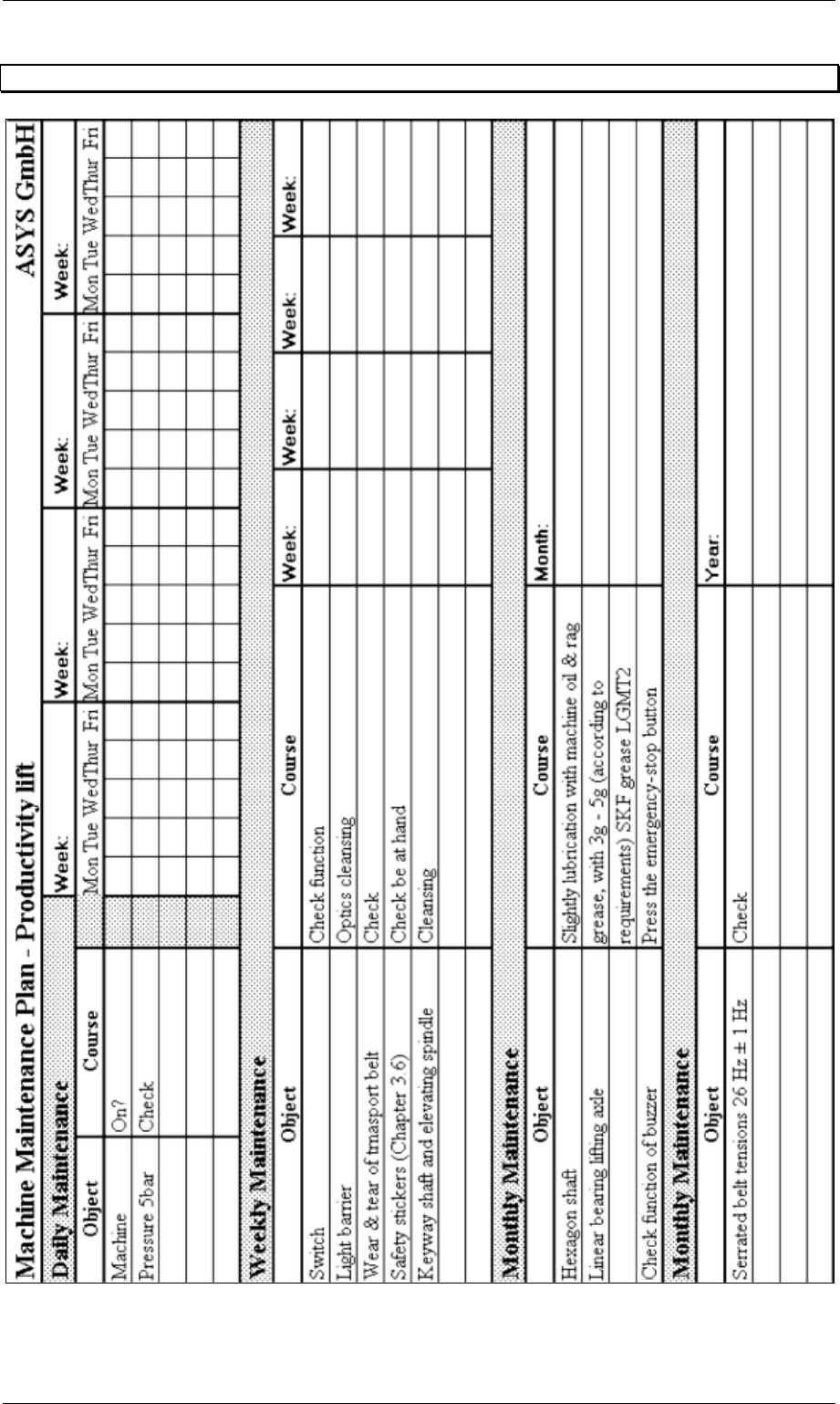
18 Appendix F Maintenance plan
For maintenance work it is absolutely necessary to observe the reference in chapter 3.5 Transport and
assembly locks.