00192169-01.pdf - 第14页
Order No. 00192 169-01 User Manual - Productivity Lift E_SPLFS03_V40_11_0300_200300_V1_14.doc Last update: 20.03.2000 - Version V 1.14 Page 14 3.4 ESD guidelines Please comply with the notes concerning the ESD guidelines…
Order No. 00192 169-01 User Manual - Productivity Lift
E_SPLFS03_V40_11_0300_200300_V1_14.doc Last update: 20.03.2000 - Version V 1.14 Page 13
The following must always be complied with:
1. A responsible person must keep the key to this switch somewhere where it is inaccessible
to others.
2. The qualified person or the service engineer may only use the key switch.
3. The key switch may only be used for the abovementioned purposes.
4. The safety key switches must be returned to service for the normal operating mode.
5. The person responsible must remove the key again.
6. The person responsible must lock the key away again.
N.B.
For safety reasons, the control cabinet doors can only be shut if the key has been removed
from the switch. In order to avoid damaging the key, particular attention must be paid to
removing the key carefully.
Set-up mode
WARNING
The fact that some safety equipment is taken out of service makes the system freely
accessible. This entails the risk of injury to people or damage to the system through
tampering. Therefore it is essential to ensure that during movements performed in the special
operating mode Installation, the equipment is not tampered with and that there are no objects
in it (e.g. tools). The qualified person or the service engineer in the installation operating
mode may only operate the equipment.
Maintenance and cleaning
ATTENTION
In order to maintain or clean the device the installation safety, described in 3.5.1, has to be
fixed and the device as well as air pressure of the filter regulation have to be switched off. The
main switch has to be locked with a personal padlock in order to avoid an unintentional switch
on. The subsequent requisite work must be carried out with due care and attention. In the
small interior space of the device, there is a slight risk that the person carrying out the work
could scratch themselves on corners or edges, although the production process does
endeavour to ensure that the parts have no sharp edges or corners.
Disconnecting compressed air supply
WARNING
Do not loosen a compressed air line without making sure that the corresponding air service
unit is pressureless by opening the handslide discharge valve or alternatively by closing the
main valve of the compressed air supply.
Code number
The code number requested in the configuration may only be known to one authorised person
and may not be passed on by this person to unauthorised persons.
3.3.2 Residual hazards for objects
There are no other factors that pose a threat to objects, property or the environment.

Order No. 00192 169-01 User Manual - Productivity Lift
E_SPLFS03_V40_11_0300_200300_V1_14.doc Last update: 20.03.2000 - Version V 1.14 Page 14
3.4 ESD guidelines
Please comply with the notes concerning the ESD guidelines as they are specified in the
operating instructions of the placement machine.
Order No. 00192 169-01 User Manual - Productivity Lift
E_SPLFS03_V40_11_0300_200300_V1_14.doc Last update: 20.03.2000 - Version V 1.14 Page 15
3.5 Transport and assembly locks
3.5.1 Disconnecting compressed air supply
WARNING
Do not loosen a compressed air line without making sure that the corresponding air service
unit is pressureless by opening the handslide discharge valve or alternatively by closing the
main valve of the compressed air supply.
3.5.2 Locking the lift belt
WARNING
The installation aid shown in the figures serves to lock the lift during servicing, maintenance
work, for example, when changing the toothed belt, and during transport. Any activity that
involves a person having to intervene in the lift area in any way should result in the following
locking measures being taken as described below. After the activities are finished and before
the device is turned on again all securities have to be removed and to be deposed at the right
place.
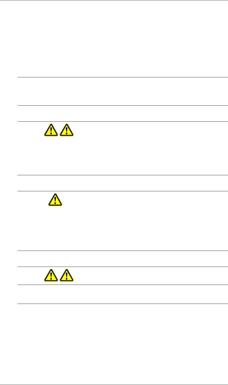
1. The following picture shows where the installation aid is kept when it is not in use.
Figure 2: Lift belt installation aid in its storage place
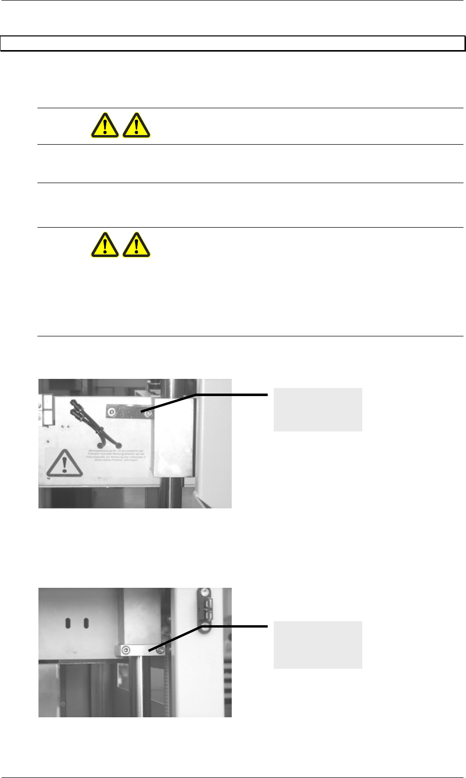
2. Before carrying out any work that is required at either of the two lift units, the installation
lock must be secured as shown in the figure below on the guide shaft underneath the lift.
To this end, the lift must be transported to its uppermost position.
Figure 3: Lift belt installation aid mounted
Installation aid in
its storage place
Locking the lift unit
using the
installation aid.